
Installation Manual Part 2

Company Proprietary
Adaptive Broadband
U-NII Product Installation Manual 05/29/2001
7-11
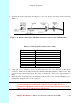
7.5.3 Connecting to the Outdoor Subscriber Unit Transceiver
Now that you have prepared the interconnect cable, you are ready to connect the cable to the
outdoor Subscriber Unit.
Attention! Always Disconnect Power from wall box BEFORE inserting RJ-45 connector
into transceiver. This prevents arcing damage from occurring.
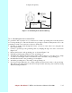
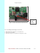
1. Insert the RJ-45 connector into the receptacle located underneath the outdoor Subscriber Unit
(refer to Figure 6-9). Make sure that the connector tab engages the slot in the receptacle.
2. Slide the grommet up the cable and press it into the bottom of the outdoor transceiver.
3. Slide the grommet clamp up the cable and align the holes with the mounting holes on the
bottom of the outdoor transceiver.
4. Insert the two screws in the mounting holes and tighten until the grommet has a slight bulge.
Be sure to tighten both screws equally so that the grommet is seated correctly.
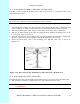
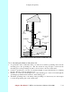
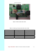
5. Secure the interconnect cable to the mounting pole with the cable clip, as shown in
Figure 7-12.
Figure 7-12 Interconnect Cable Installation to Subscriber Unit -- Bottom View
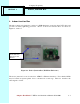
7.5.4 Connecting to the Indoor Junction Box
Note that the junction box should still be disassembled and not screwed to the wall at this point.
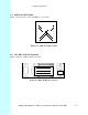
1. Strip 2 inches of insulation off the junction box end of the interconnect cable.
Attention! Don’t cut off the shield from the cable – you will need it to ground the
system later.