
Installation Manual Part 2

Company Proprietary
Adaptive Broadband
U-NII Product Installation Manual 05/29/2001
7-10
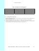
4. Separate the twisted pair wires and align by color code in the order listed in the following
Table 7-7.
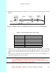
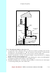
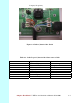
Figure 7-11 Outdoor Subscriber Unit End of the Interconnect Cable with Shielding
Table 7-7 Cable Legend for Interconnect Cable
Pin Color Code
1 White / Orange
2 Orange
3 White / Green
4Blue
5 White / Blue
6 Green
7 White / Brown
8Brown
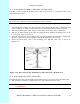
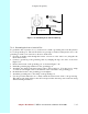
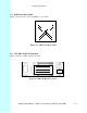
5. Using pin 1 as a reference, insert the individual wires into the channels of the RJ-45
connector. Each wire should penetrate the channels until flush with the connector end. The
copper foil tape should extend past the casing of the RJ-45 connector by approximately ½
inch.
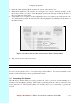
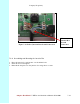
6. When all wires are inserted into the channels in their correct order, use the crimping tool to
permanently crimp the wires to the connector.
Attention! Carefully read the instructions for the crimping tool you are using. Use the
correct crimping tool for the RJ-45 connector you are using. Incorrect
installation of the RJ-45 connector may result in a bad connection between the
outdoor transceiver and the indoor junction box.