
Installation Manual Part 2

Company Proprietary
Adaptive Broadband
U-NII Product Installation Manual 05/29/2001
7-9
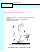
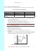
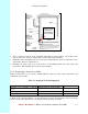
NOTE: The Grommet is made of a special conductive material used to complete
the ground between the Subscriber Unit and indoor junction box.
Figure 7-9 Grommet Location -- Underside of Subscriber Unit
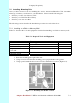
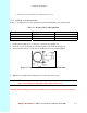
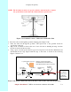
2. Insert the cable end through the grommet clamping plate (Figure 7-10).
1. Insert the cable end through the grommet. The tapered end of the grommet should be
opposite the cable end.
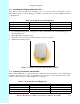
2. Strip 1 inch of insulation off the cable end. Leave 3/8 inch of shielding showing, and trim
the wire ends flat ½ inch from there.
3. Using a piece of 1inch squared tinned copper foil, wrap the foil around the shield/braid and
sheath with the left edge aligned with the edge of the braid, as shown in the following
Figures 7-10 and 7-11.
Figure 7-10 Outdoor Subscriber Unit of the Interconnect Cable with Cable Preparation
Grommet
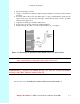
Grommet
clamping
plate
Note direction
of taper
Insert wire
into channels
1/2"
3/8"
Shielding
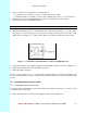
Pin 1
Tab on
underside
1" square tinned copper foil - wrap the copper foil around the
shield/braid and sheath with the left
edge aligned with the edge of the braid.
Grommet is
conductive
and used to
complete
the ground