
Installation Manual Part 1


Company Proprietary
Adaptive Broadband
U-NII Product Installation Manual 05/29/2001
6-10
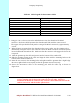
Table 6-3 Cable Legend for Interconnect Cable
Pin Color Code
1 White / Orange
2 Orange
3 White / Green
4Blue
5 White / Blue
6 Green
7 White / Brown
8Brown
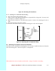
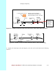
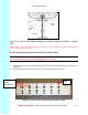
7. Using pin 1 as a reference, insert the individual wires into the channels of the RJ-45
connector. Each wire should penetrate the channels until flush with the connector end.
The copper foil tape should extend past the casing of the RJ-45 connector by approximately
½ inch.
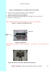
8. When all wires are inserted into the channels in their correct order, use the crimping tool to
Permanently crimp the wires to the connector. Insert the RJ-45 connector into the receptacle
located underneath the outdoor EX. Make sure that the connector tab engages the slot in the
receptacle.
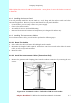
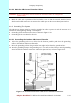
13. Slide the grommet up the cable and press it into the bottom of the outdoor EX.
14. Slide the grommet clamp up the cable and align the holes with the mounting holes on the
bottom of the outdoor transceiver.
15. Insert the two screws in the mounting holes and tighten until the grommet has a slight bulge.
Be sure to tighten both screws equally so that the grommet is seated correctly.
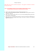
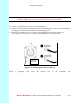
16. Secure the interconnect cable to the mounting pole with the cable clip as shown in
Figure 6-14.
Attention! Carefully read the instructions for the crimping tool you are using. Use the
correct crimping tool for the RJ-45 connector you are using. Incorrect
installation of the RJ-45 connector may result in a bad connection between the
outdoor transceiver and the indoor junction box.