
Installation Manual Part 1

Company Proprietary
Adaptive Broadband
U-NII Product Installation Manual 05/29/2001
4-4
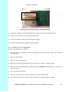
4. Insert the DB-9 to RJ-45 adapter into the COM2 port on the Control Server. Connect from
the Console port on the anchor switch to the DB-9 to RJ-45 adapter on the COM2 port of the
Control Server.
5. Connect the mouse and keyboard to the Control Server.
6. Connect your monitor’s signal cable to the monitor port on the Control Server.
7. Connect the power cords for the Control Server, anchor switch, indoor junction box and
monitor to AC wall outlets, but
do not switch on
.
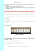
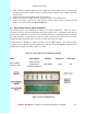
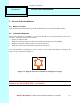
4.4 Base Station Access Panel Installation
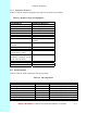
The following steps cover installing the indoor Access Panel installation. Table 4-3 gives a
description of the Access Panel and Figure 4-2 shows a photo of it. As designed, these Access
Panels exactly duplicate the circuitry of the existing wall boxes. Installation follows the same
directions. However, no punch down of the STP cable is needed on the radio side of the panel.
Straight through CAT5 STP cables are used to connect the panel to the radio.
The patch panel is designed to replace six wall boxes in a Base Station. The Artesyn power
supplies are to be replaced by power supplies such as Kepco’s (part #PS-RM0101-1000953) rack
mounted power supply operating at 48 V - 3.6 A DC.
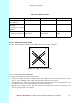
Table 4-3 Base Station Access Panel Description
Name Description Model # Revision # CLEI code
Base Station
Access Panel
Access Panel
Rack Mount
6 AP/EX Interfaces
WB-05001 v1.00 NA
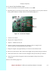
Figure 4-2 Access Panel Ports