
Installation Manual Part 1

Company Proprietary
Adaptive Broadband
U-NII Product Installation Manual 05/29/2001
4-3
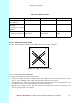
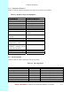
Table 4-2 Required Cables
Cable Run Cable Type No. Required Connectors
AS port 101 to
CS ATM port
CAT5 1 RJ-45
AS Console port to
CS COM
(via DB-9 to RJ-45
adapter)
CAT5 1 RJ-45
AS ports 102, 103 etc.
to indoor junction box
ATM
Cross-over
Same as number of
transceivers
RJ-45 – see below for
pinout
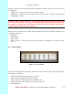
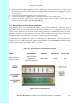
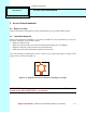
4.3.2.1 ATM Cross-Over Cable
The pin connections for making up an ATM cross-over cable are as follows:
Figure 4-1 ATM Cross-Over Cable
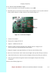
4.3.3 Connecting The Equipment
To connect the equipment, proceed as follows:
1. Connect from port 101 on the anchor switch to the ATM port on the rear panel of the Control
Server. Use a standard CAT5 cable with an RJ-45 connector on each end.
2. Connect from port 102 on the anchor switch to the appropriate port on the access panel. Use
an ATM cross-over cable with an RJ-45 connector on each end.
3. Repeat step 2, using ports 103, 104, 201, 202, 203 and 204, until you have connected to all
the ‘live’ ports on the access panel.
Pin
1
2
3
4
5
6
7
8
Pin
1
2
3
4
5
6
7
8