
Installation Manual Part 1

Company Proprietary
Adaptive Broadband
U-NII Product Installation Manual 05/29/2001
4-2
4.2.1 Anchor Switch
The Anchor Switch is an Access NGI WAN Access Switch, model VSW 200E, from
FVC>COM. The box should contain:
• Anchor Switch
• V-Switch User’s Guide
• Power cord
• Serial port adapter.
4.2.2 Control Server
The Control Server is a Dell PowerEdge 2450. The box should contain:
• Control Server.
• Mouse.
• Keyboard
• Software installation CD-ROMs (note that all necessary software has been preinstalled)
• Two power cords
• Keys for accessing drive bays and internal upgrade options (see below for key locations).
• Manuals, including the Dell 1 x 8 Backplane Option leaflet.
4.2.2.1 Key Locations
The keys supplied with the Control Server are located as follows:
• 4300 – Behind the “4300” label on the front panel; press the label to open the hidden
compartment.
• 4350 – On a hanger on the rear panel
• 2450 – On a hanger on the rear panel.
4.3 Installing The Equipment
This section explains how to connect up the anchor switch, Control Server and outdoor
transceivers.
4.3.1 Position The Equipment
After unpacking all the equipment, position the anchor switch and Control Server so as to
minimize the distances between them, the indoor junction box, and your power outlets. You may
want to rack mount the anchor switch and Control Server. Please see the V-Switch User’s Guide.
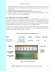
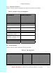
4.3.2 Making Up Connecting Cables
The following Table 4-2 shows the various types and lengths of cable.