
Installation Manual Part 1

Company Proprietary
Adaptive Broadband
U-NII Product Installation Manual 05/29/2001
3-4
between the anchor switch and the network management software. The ports on the rear panel
are as follows:
• ATM25 port – Connects to port 101 on the anchor switch.
• COM2 port – Connects to the Console port on the anchor switch. Used for monitoring and
configuring the switch.
Attention!
This is a DB-9 connector. First, plug the DB-9 to RJ-45 adapter (supplied with
FVC switch) into this port, then plug a straight through patch cable from the switch into
the adapter. It is important to note that the user must use the FVC supplied serial adapter,
as other adapters may not operate correctly!
Please see the V-Switch User’s Guide (supplied with the switch) for detailed information on
configuring the switch.
• Mouse port
• Keyboard port
• Monitor port
• Power connector – There may be one or three of these, depending on your model Control
Server.
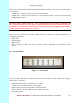
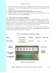
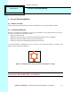
3.6 Access Panel
Figure 3-5 Access Panel
The Access Panel provides an interface between the Anchor Switch (AS), a 48V power supply,
and the APs. It includes:
• Rack-mounted unit that can handle up to six APs
• Connects to a redundant 48V DC power supply
• RJ-45 connectors to take interconnect cables from APs
• RJ-45 connectors to take ATM cross-over cables to the AS
• Grounding points