
Installation Manual Part 1

Company Proprietary
Adaptive Broadband
U-NII Product Installation Manual 05/29/2001
xi
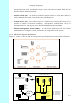
Figure 1-1 AB-Access Typical Deployment................................................................................1-2
Figure 1-2 AB-Access Typical Network Architecture................................................................1-3
Figure 2-1 Outdoor Subscriber Unit Components .......................................................................2-3
Figure 2-2 Access Point Locations.............................................................................................2-5
Figure 2-3 Aligning the Compass and Map ...............................................................................2-6
Figure 2-4 Selecting an Access Point.........................................................................................2-7
Figure 3-1 Base Station Overview ...............................................................................................3-1
Figure 3-2 Outdoor Access Point and Mounting Pole ................................................................3-2
Figure 3-3 Anchor Switch Front Panel .......................................................................................3-2
Figure 3-4 Dell 2450 Control Server Rear Panel........................................................................3-3
Figure 3-5 Access Panel..............................................................................................................3-4
Figure 4-1 ATM Cross-Over Cable.............................................................................................4-3
Figure 5-1 Diagram of Six Access Points for 360 degree Coverage...........................................5-1
Figure 5-2 Outdoor Access Point Components...........................................................................5-3
Figure 5-3 Access Panel used as Patch Panel .............................................................................5-3
Figure 5-4 Mounting Pole Installed on Pole or Antenna Mast ...................................................5-4
Figure 5-5 Mounting Pole Installation ........................................................................................5-5
Figure 5-6 Mounting Pole on Clapboard Siding.........................................................................5-5
Figure 5-7 Mounting Parts for an Outdoor Access Point............................................................5-6
Figure 5-8 Access Point Rear View............................................................................................5-6
Figure 5-9 Tilt Bracket................................................................................................................5-7
Figure 5-10 Access Point with Mounted Tilt Bracket ................................................................5-7
Figure 5-11 Grommet Location - Underside of Access Point.....................................................5-8
Figure 5-12 Outdoor Transceiver End of the Interconnect Cable with Cable Preparation.........5-9
Figure 5-13 Outdoor Transceiver End of the Interconnect Cable with Shielding.......................5-9
Figure 5-14 Interconnect Cable Installation to Outdoor Access Point - Bottom View.............5-11
Figure 5-15 Access Panel showing Connections to Access Point............................................5-11
Figure 5-16 Ground Connections to Access Point Transceiver................................................5-12
Figure 5-17 Mounting Pole with Ground Lug...........................................................................5-13
Figure 6-1 Outdoor AB-Access Extender Components..............................................................6-3
Figure 6-2 Access Panel used as Patch Panel .............................................................................6-3
Figure 6-3 Mounting Pole Installed on Pole or Antenna Mast ...................................................6-4
Figure 6-4 Mounting Pole Installation ........................................................................................6-5
Figure 6-5 Mounting Pole on Clapboard Siding.........................................................................6-5
Figure 6-6 Mounting Parts for an Outdoor AB-Access Extender...............................................6-6
Figure 6-7 AB-Access Extender Rear View ...............................................................................6-6
Figure 6-8 Tilt Bracket................................................................................................................6-6
Figure 6-9 AB-Access Extender with Mounted Tilt Bracket......................................................6-6
Figure 6-10 Grommet Location - Underside of AB-Access Extender........................................6-7
Figure 6-11 Outdoor Transceiver End of the Interconnect Cable with Cable Preparation.........6-9
Figure 6-12 Outdoor Transceiver End of the Interconnect Cable with Shielding.......................6-9
AB-ACCESS SYSTEM
LIST OF FIGURES