
User's Manual

Copyright 2015 Axxcelera Broadband Wireless, Inc. All rights reserved
AxxceLTE eNodeB
Installation Guide v1.0 - 6 -
2.3 System Components
2.3.1 System Architecture
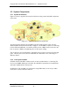
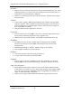
Figure 3.1 shows a typical LTE network architecture using various eNodeB components
at the tower.
Figure 2.1 – Typical LTE Network Architecture
As is shown in the diagram, the eNodeB is typically deployed at the tower, near any
additional RRH units and antennas that it supports. As the BBU is capable of connecting
to three different RRH units, it would be possible to have a BBU located at one site and
have it connect a RRH at a neighboring site via fiber optic cabling.
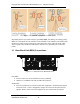
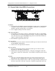
The S1 interface exits the UPLINK1 / UPLINK2 port(s) which are field serviceable SFP
ports. The two ports can be used for redundant S1 connections or for connecting to 2
different μEPCs.
2.3.2 Time synchronization
Included with the eNodeB is a GPS receiver for time synchronization. Connecting the
receiver to the BBU “GPS” port will allow the eNodeB to synchronize its transmissions
with other eNodeB units in the network.
In addition to GPS, the BBU can synchronize using IEEE 1588, or can accept a 1PPS
clock source via the SYNCIN connector.