
User's Manual

Copyright 2015 Axxcelera Broadband Wireless, Inc. All rights reserved
AxxceLTE eNodeB
Installation Guide v1.0 - 15 -
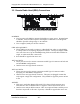
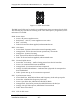
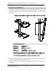
Figure 6.1 – BBU Panel LEDs
The BBU panel LEDs can be valuable in troubleshooting issues encountered in the field.
The following key describes the meaning of the color and sequence (if applicable) of the
indication at each LED.
PWR: Power Status
· Green: All power supplies active
· Red/Green: +12V on, some supplies are not active
· Red: +12V only
· Dark: No Power has been applied, undetermined state.
RDY: CPU Status
· Green Dash: System is alive and in normal operating mode
· Orange Dash: CPU is alive and in non-operational / test mode
· Orange Dot: System is booting
· Red: System boot failed or fatal assertion.
· Dark: No Power has been applied, undetermined state
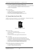
UPL: Network Uplink Status
· Green Dot: S1 Activity – traffic is being passed over the S1 Interface
· Green: S1 connection has been established
· Orange Dash: S1 connection has been requested
· Orange: S1 GbE Link indicator – indicates that a physical S1 transport has
been established
· Dark: System not up; no S1 connection requested
SNC: Synchronization Status
· Green Dash Dot: AD9548 has Phase and Frequency Lock with sync pulse
· Green Dot: AD9548 has Frequency Lock only
· Green: Sync Pulse lost; AD9548 is in Holdover Mode
· Orange Dash: Sync Pulse present, but AD9548 has not locked yet
· Orange: No Sync Pulse preset; AD9548 in Freerun Mode
· Dark: None of the above
UUL: LTE Uu link status