
User's Manual
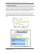

Copyright 2015 Axxcelera Broadband Wireless, Inc. All rights reserved
AxxceLTE eNodeB
Installation Guide v1.0 - 16 -
· Green Dot: CPRI link active; PDSCH or PUSHC activity
· Green: CPRI link established with RRH; TTI indications received (sub-frame
counter is incrementing); no PDSCH or PUSHC activity detected
· Dark: No TTI indications
ALM: Alarm Status
· Green: No alarms
· Orange: One or more non-fatal alarms are present
· Red: One or more fatal alarms are present
· Dark: No power has been applied, undetermined state
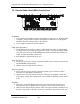
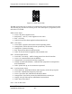
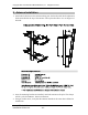
6.3 Remote Radio Head Panel LEDs
Included on the remote radio head are a set of LED Indicators. The figure below shows
the layout of these LEDs on the bottom panel of the RRH.
Figure 6.2 – RRH Panel LEDs
PWR: Power Status
· Green: All power supplies active
· Red/Green: +12V on, some supplies are not active
· Red: +12V only
· Dark: No Power has been applied, undetermined state.
CPU: CPU Status
· Green Dash: CPU is alive and in normal operating mode
· Orange Dash: CPU is alive and in non-operational / test mode
· Orange Dot: CPU booting (including any associated provisioning)
· Red: System boot failed or fatal assertion has occurred
· Dark: No power has been applied, undetermined state
C&M: CPRI Configuration and Management link Status
· Green/Orange: Receive and Transmit
· Orange: Transmit data (min 50ms on)