
User's Manual
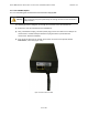
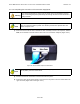
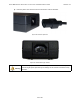
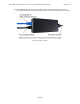
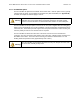
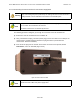
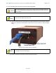
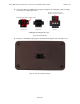
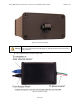
Table Of Contents
- 1.0 Preface
- 2.0 Introduction
- 3.0 Installation
- 3.1 Compliance Alert - Operation in the 3.4 - 3.6 GHz Band
- 3.2 Operation in the 3.650 - 3.675 GHz Band
- 3.3 Installation Warnings
- 3.4 Environmental Cautions
- 3.5 Installing Outdoor Equipment
- 3.6 Installing an Optional Sector Antenna
- 3.7 Installing Optional Omnidirectional Antenna
- 3.8 Installing the Access Point
- 3.9 Power and Data Connections - AC and DC Power Options
- 4.0 Configuring an Access Point for Single-Channel Use
- 5.0 Maintenance Guide
- Appendix A: NIA/Power Adapter Specifications: Model # TR60A-POE-L
- Appendix B: ExcelMax DC PSU/NIA (020-44109-0802)
- Appendix C: Glossary of Terms and Abbreviations

EXCELMAX ACCESS POINT CELL INSTALLATION AND MAINTENANCE GUIDE VERSION 1.4
48
OF 65
3) Screw three wires (22-14AWG) from the power supply into the mating plug (-48V DC supply,
DC return, and earth) (Figure 3-25:).
Figure 3-25: Mating Power Plug
4) Connect the assembled mating plug into the DC PSU/NIA (Figure 3-26: and Figure 3-27:).
Figure 3-26: NIA’s connector without mating plug
Exterior View Mating View Top View
Mating Power Plug Connector
-48V DC Supply, DC Return, and Earth Ground
Clamping screws for DC Supply,
DC Return , and Earth Ground wires