
User's Manual
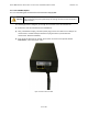
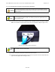
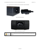
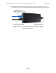
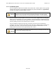
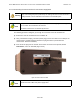
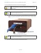
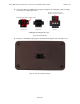
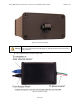
Table Of Contents
- 1.0 Preface
- 2.0 Introduction
- 3.0 Installation
- 3.1 Compliance Alert - Operation in the 3.4 - 3.6 GHz Band
- 3.2 Operation in the 3.650 - 3.675 GHz Band
- 3.3 Installation Warnings
- 3.4 Environmental Cautions
- 3.5 Installing Outdoor Equipment
- 3.6 Installing an Optional Sector Antenna
- 3.7 Installing Optional Omnidirectional Antenna
- 3.8 Installing the Access Point
- 3.9 Power and Data Connections - AC and DC Power Options
- 4.0 Configuring an Access Point for Single-Channel Use
- 5.0 Maintenance Guide
- Appendix A: NIA/Power Adapter Specifications: Model # TR60A-POE-L
- Appendix B: ExcelMax DC PSU/NIA (020-44109-0802)
- Appendix C: Glossary of Terms and Abbreviations

EXCELMAX ACCESS POINT CELL INSTALLATION AND MAINTENANCE GUIDE VERSION 1.4
46
OF 65
3.9.2.1 Connecting the Access Point to the DC Power Supply/NIA
The following procedures will guide you through the connection of the DC PSU/NIA unit:
1) Rem
ove the new DC PSU/NIA from the installation kit.
2) Using a shielded RJ-45 plug, terminate (attach plug) to the Access Point Cat-5 cable per the
manufacturer's recommended specifications for plug attachment. (Recommended
manufacturer: AMP P/N 5-569552).
3) Insert the RJ-45 plug from the outdoor Access Point into the RJ-45 receptacle, labeled
Data+Power, on the DC PSU/NIA (Figure 3-23:).
Figure 3-23: Connect the Access Point
Warning
It is extremely important to connect the DC power to the DC PSU/NIA as the last
step. Co
nnecting DC power prematurely can damage the Access Point and lead to
faulty behavior.
The DC PSU/NIA unit contains no serviceable parts.
Note
The power should be tested - the power (outer
) LED should light green. If the light is
red or off then the connections are incorrect.
The Earth connection is not checked by the LED.
Note
Th
e DC PSU/NIA does not come with cables or power cord. Service provider must
provide their own cables and power supply wires.
N
N