
User's Manual
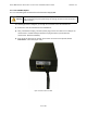
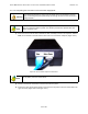
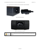
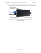
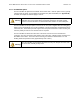
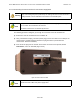
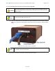
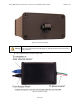
Table Of Contents
- 1.0 Preface
- 2.0 Introduction
- 3.0 Installation
- 3.1 Compliance Alert - Operation in the 3.4 - 3.6 GHz Band
- 3.2 Operation in the 3.650 - 3.675 GHz Band
- 3.3 Installation Warnings
- 3.4 Environmental Cautions
- 3.5 Installing Outdoor Equipment
- 3.6 Installing an Optional Sector Antenna
- 3.7 Installing Optional Omnidirectional Antenna
- 3.8 Installing the Access Point
- 3.9 Power and Data Connections - AC and DC Power Options
- 4.0 Configuring an Access Point for Single-Channel Use
- 5.0 Maintenance Guide
- Appendix A: NIA/Power Adapter Specifications: Model # TR60A-POE-L
- Appendix B: ExcelMax DC PSU/NIA (020-44109-0802)
- Appendix C: Glossary of Terms and Abbreviations

EXCELMAX ACCESS POINT CELL INSTALLATION AND MAINTENANCE GUIDE VERSION 1.4
42
OF 65
3.9.1.2 Completing the Connection of the AC Power Supply/NIA
1) Inser
t one end of an RJ-45 to RJ-45 Ethernet cable assembly to the RJ-45 receptacle, labeled
Data, on the outside of the NIA and the other end to the customer's computer (Figure 3-19:).
Figure 3-19: Connect customer computer or network device
2) Check to see that the connection to the Access Point is in place.
3) Connect the three-prong female power cord to the NIA. The power cord uses an IEC-320-C13
type connector (Figure 3-20: and Figure 3-21:).
Warning
It is extremely important to connect the AC power to the AC PSU/NIA as the last
step. Connecting AC power prematurely can damage the Access Point and lead to
faulty behavior.
Note
Other than the models where the power supply cord
is included, the AC PSU/NIA
does not come with cables or power cord. Service provider must provide their own
cables and power cord.
Note
Custome
r equipment requiring Ethernet connectivity may not be located more than
100 m (328 ft.) from the Access Point.
N
N