
User's Manual
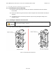
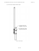
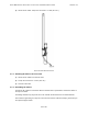
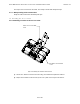
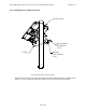
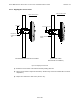
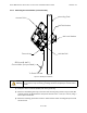
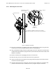

Table Of Contents
- 1.0 Preface
- 2.0 Introduction
- 3.0 Installation
- 3.1 Compliance Alert - Operation in the 3.4 - 3.6 GHz Band
- 3.2 Operation in the 3.650 - 3.675 GHz Band
- 3.3 Installation Warnings
- 3.4 Environmental Cautions
- 3.5 Installing Outdoor Equipment
- 3.6 Installing an Optional Sector Antenna
- 3.7 Installing Optional Omnidirectional Antenna
- 3.8 Installing the Access Point
- 3.9 Power and Data Connections - AC and DC Power Options
- 4.0 Configuring an Access Point for Single-Channel Use
- 5.0 Maintenance Guide
- Appendix A: NIA/Power Adapter Specifications: Model # TR60A-POE-L
- Appendix B: ExcelMax DC PSU/NIA (020-44109-0802)
- Appendix C: Glossary of Terms and Abbreviations

EXCELMAX ACCESS POINT CELL INSTALLATION AND MAINTENANCE GUIDE VERSION 1.4
38
OF 65
3.8.5 Attaching the Cat-5 Cable
Figure 3-17: Attaching the Cat-5 Cable
1) Push the un-terminated, un-stripped (no plug) Cat-5 cable through the hole in the gland seal.
Loosen the nut on top of the gland seal if the wire is not moving freely.
2) Using a shielded RJ-45 plug, terminate (attach plug) to the Cat-5 cable per the manufacturer's
recommended specifications for plug attachment. (Recommended manufacturer: AMP, P/N 5-
569552 or equivalent)
3) Remove and discard the cap plugging the hole in the transceiver.
4) Slide the O-ring over the Cat-5 cable and onto the PG-11 gland seal.
5) Look into the open hole and orient the RJ-45 plug, pushing the plug into the socket until the
connectors are locked together.
6) Thread the gland seal into the transceiver and torque using the bottom nut of the gland seal
(closest to the Access Point) to 3.8 Nm (33.2 in.-lb.) using the 7/8 open-end wrench.
Cap
Shielded RJ-45 Plug
(not provided)
Access Point
UV-resistant, shielded, outdoor Cat-5 Cable
O-ring
PG-11 Gland
Seal
DETAIL A
SCALE 1 : 2
A
(Ø5.2-4.8 mm [Ø.205-.190 in] to IDU (not provided)