
User Guide
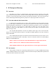
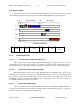
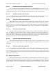
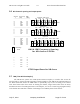
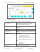
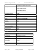
Table Of Contents
- Revision History
- PLEASE READ THESE SAFETY PRECAUTIONS!
- Document Overview
- AB-Access Overview
- AB-Access
- RF Design and Planning
- Static Configurations
- CLIP_T
- CLIP_S
- Hybrid CLIP_S
- 1483_T
- 1483_S
- Native ATM
- Extender
AB-Access Config & User Guide 5.5 Axxcelera Broadband Wireless
July 27, 2004 Company Confidential Page 28 of 129
• Spectral Efficiency – TDD can be deployed using less spectrum than a comparable FDD
system. A single TDD channel can be deployed per sector instead of two channels needed
for FDD. Likewise, a multi-cell deployment can be installed using a total of three RF
channels (both polarizations), whereas FDD needs four to six channels.
• Complexity – Since each transceiver is wither transmitting or receiving, but never both at
once, a single RF front end can be shared reducing the radio complexity.
• Power Control – In cellular systems, where channels are reused many times throughout
the system in order to increase capacity, the highest efficiency is realized when the power
in each direction can be minimized. This reduces the amount of energy that is ‘leaked’
into surrounding areas, which appears as interference. In FDD systems, it is quite difficult
to accurately control the channel’s power since a feedback path is required. No such path
is needed in a TDD system since the same channel is used in both directions. The SU
needs to only measure the received power from the AP in order to know how much to
attenuate its upstream transmission.
• Channel Efficiency – Because each frame carries upstream and downstream traffic in
proportion to the offered load in each direction, adaptive TDD systems are highly
efficient in its use of bandwidth. FDD systems have to make an estimate of the traffic
mixture and allocate channel bandwidth accordingly. As shown in the chart below, any
variation from this estimate (in this case 15:1 downlink) will result in wasted bandwidth.
This variation is inevitable due to the diurnal variation of business usage during the
daytime hours, residential usage in the afternoon and evening, a varying mixture of user
types according to the geographic location, and an ever-changing set of user applications.
5.8
AP and SU Specifications
5.8.1
AP/SU/Extender Functional Block Diagram
The Access Point and Subscriber Unit functional block diagram is shown below. The analog
radio portion is highlighted in blue, while the digital section containing the modem is in
yellow.