
User Guide
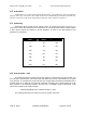
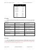
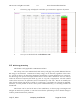
Table Of Contents
- Revision History
- PLEASE READ THESE SAFETY PRECAUTIONS!
- Document Overview
- AB-Access Overview
- AB-Access
- RF Design and Planning
- Static Configurations
- CLIP_T
- CLIP_S
- Hybrid CLIP_S
- 1483_T
- 1483_S
- Native ATM
- Extender

AB-Access Config & User Guide 5.5 Axxcelera Broadband Wireless
July 27, 2004 Company Confidential Page 14 of 129
4.2
ATM Switch
ATM switches are referenced throughout this document. The ATM switch used for illustration
purposes is the FVC Access NGI. The switch used for the troubleshooting screenshots represents FVC
software version 5.07. Some of the commands for older FVC switch software are different.
4.3
Subnetting
Subnetting within the AB-Access radios is done in hexadecimal format. There for it is
necessary to know the decimal to hex conversions for commonly used subnets. CIDR notation
is also used to define the subnets in all the diagrams, so refer to the chart below for any
questions on subnetting.
Decimal
Subnet
HEX
Subnet
CIDR
0 00 /24
128 80 /25
192 C0 /26
224 E0 /27
240 F0 /28
248 F8 /29
252 FC /30
4.4
Peak Cell Rate - PCR
The Peak Cell Rate is policing not pacing, there for it will discard all cells received over
the limit and not buffer them. This means the cells will be have to be retransmitted via an upper
layer protocol. To calculate the Peak Cell Rate you simply divide the desired bandwidth by the
number of bits in an ATM cell. An ATM cell is 53 bytes consisting of a 5-byte header and a 48-
byte payload. In the following example, the PCR for a 1 Megabit circuit is calculated. PCR
values are rounded to the nearest integer.
1024000 bps/(48 bytes-per-cell*8 bits-per-byte) = 2667
The following table lists PCR values for several, common data rates.