
User Guide
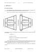
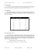
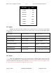
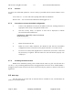
Table Of Contents
- Revision History
- PLEASE READ THESE SAFETY PRECAUTIONS!
- Document Overview
- AB-Access Overview
- AB-Access
- RF Design and Planning
- Static Configurations
- CLIP_T
- CLIP_S
- Hybrid CLIP_S
- 1483_T
- 1483_S
- Native ATM
- Extender

AB-Access Config & User Guide 5.5 Axxcelera Broadband Wireless
July 27, 2004 Company Confidential Page 13 of 129
4 AB-Access
4.1
Reference Model
The diagram below is the architectural reference model for this document. Depending upon
the required architecture, certain layers of this model may or may not be used.
Please note that both the wireless and terrestrial interfaces have access to all of the
functions of the unit. This is designed to allow the reader to understand where an incoming service
is terminating and where its configuration is managed. Management files (on Flashfs) for each layer
are as follows:
All: system.conf
Routing Layer: resolve
Bridging Layer: resolve, initbridge, initmr1483 or initr1483
Switching Layer: initswitchcli
An E or A will indicate the Terrestrial interface type below the interface at the corner. As an
example, the diagram above shows an SU (on the left) with an Ethernet terrestrial interface and an
AP (on the right) with an ATM interface. The Wireless interface is always ATM.
Additional services/clients such as NAT and/or DHCP will be depicted at the appropriate
interface.