
Trouble Shooting Guide
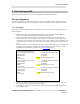
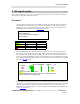
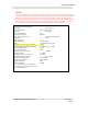
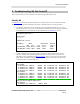
Table Of Contents
- Troubleshooting-Installing an RF link
- Issue : 5.3.x
- Authors : Matt Olson/Dave Sida
- Date : 30th July 2004
- CONTENTS
- CHANGE HISTORY
- INTRODUCTION
- Aligning an SU
- Fine tuning an SU
- SU signal quality
- Troubleshooting SU link from AP
- Link status
- AP Link Status
- SU Link Status
- MAC type
- Unit MAC address
- Channel
- Radio Channel Mask
- Correlation sequence
- MAC delay compensation
- Unit Range
- Base Station ID
- Radio Temperature
- RSSI
- Path loss in excess of FSL (estimate)
- Downlink RSSI Fade Margin
- TX maximum backoff
- TX current backoff
- Max TX power for channel
- Actual TX power
- Averaging MAC error rates over
- Downlink Header Error Rate
- Downlink Cell Error Rate
- Uplink Cell Error Rate
- Modem RSSI
- Mac stats
- Modem txpower
- Modem mmse
- PNMS Sector
- Survey Scan
- Modem msreg 6 1
- Modem rxdc stats
- Bun list channels

Axxcelera Broadband
Troubleshooting-Installing an RF link - 20 - Issue: 5.3.x
Rev 2
7.1.17 Radio Channel Mask
Radio Channel Mask displays the current channel mask. The channel mask determines which channels will
be scanned in dynamic mode and when the survey web page is used.
7.1.18 Correlation sequence
Correlation sequence displays whether or not the SU modem has detected a downstream burst (the
“training/correlation sequence”) from the AP modem. This has to happen before the MAC can delay
compensate. If the correlation sequence is un-detected you will never get a RF link. The SU can correlate
even when the received signal is too weak to decode the rest of the burst. Failure to correlate indicates that
the SU cannot detect the presence of an AP. This may be caused by the AP being off-line, an AP-SU
alignment or line-of-sight problem, the AP and SU operating on different channels or polarisations, or a
major error in the SU software configuration or hardware.
7.1.19 MAC delay compensation
MAC delay compensation will inform you if the MAC has delay compensated. It will also display the
distance in metres that it had to back itself off to appear at the edge of the sector. The delay compensation
value is inversely related to the AP-SU separation.
7.1.20 Unit Range
Unit Range displays the distance that the SU is from the AP in km. This measurement is based on the
delay compensation value and is only an approximate value.
7.1.21 Base Station ID
Base Station ID is not currently used and can be ignored.
7.1.22 Radio Temperature
Radio Temperature displays the internal temperature of the radio in degrees Celsius. It is followed by an
indicator to tell you if the temperature is acceptable. Possible indicators are good, marginal and bad.
7.1.23 RSSI
RSSI is the Receiver Signal Strength Indicator, and is displayed in dBm. It is followed by an indicator to
tell you if the signal strength is acceptable.
7.1.24 Path loss in excess of FSL (estimate)
This shows the path loss (dB) in excess of the expected free-space loss (FSL) for the AP-SU distance.
This value is approximately 0dB for a perfectly aligned AP and SU, regardless of the AP-SU distance.
Although the RSSI may be strong, a high value here may indicate that the SU and AP are not well aligned
and the quality of the RF link may be compromised as a result. A value greater than 10dB should cause
concern. Possible causes are the AP and SU set to opposight polarisations, obstructed line-of-sight, SU
lying outside the main RF beam from the AP (either horizontal or vertical planes), or the SU antenna being
misaligned with the AP. The calculation of this value relies on the AP and SU having the same system