
Install Manual
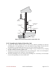
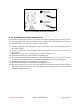
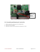
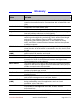
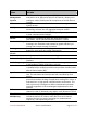
Table Of Contents
- Preface
- PLEASE READ THESE SAFETY PRECAUTIONS!
- Table of Contents
- List of Figures
- List of Tables
- AB-Access Product Overview
- Getting Started
- Base Station Installation
- Access Point Installation
- AB-Extender Installation
- Subscriber Unit Installation
- Indoor Junction Box
- Glossary
- Acronyms/Abbreviations

Axxcelera Broadband Product Install Manual Page 65 of 71
The indoor junction box can be wired for ATM25 or Ethernet interfaces. Note that the PCBs
may be housed in separate plastic boxes or mounted in a card cage. Table 7-1 describes the
cable legend to follow.
Table 7-1 Cable Legend - Junction Box Interconnect Cable
Pin Signal Color Code
1 Transmit High (+) White / Orange
2 Transmit Low (-) Orange
3 LED2 White / Green
4 Supply Minus Blue
5 Supply Plus White / Blue
6 LED1 Green
7 Receive High (+) White / Brown
8 Receive Low (-) Brown
7.1 ATM Cross-Over Cable
Figure 7-3 shows how to wire an ATM cross-over cable:
Figure 7-3 ATM Cross-Over Cable
7.2 FVC DB-9 to RJ-45 Converter
Figure 7-4 shows a DB-9 to RJ-45 converter.
Figure 7-4 DB-9 To RJ-45 Converter
2----------------------------------------3
3----------------------------------------7
5----------------------------------------5