
Install Manual
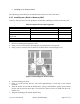
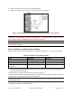
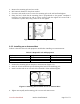
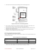
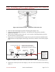
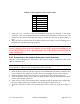
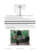
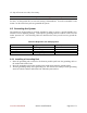
Table Of Contents
- Preface
- PLEASE READ THESE SAFETY PRECAUTIONS!
- Table of Contents
- List of Figures
- List of Tables
- AB-Access Product Overview
- Getting Started
- Base Station Installation
- Access Point Installation
- AB-Extender Installation
- Subscriber Unit Installation
- Indoor Junction Box
- Glossary
- Acronyms/Abbreviations

Axxcelera Broadband Product Install Manual Page 58 of 71
Table 6-7 Cable Legend for Interconnect Cable
Pin Color Code
1 White / Orange
2 Orange
3 White / Green
4 Blue
5 White / Blue
6 Green
7 White / Brown
8 Brown
7. Using pin 1 as a reference, insert the individual wires into the channels of the RJ-45
connector. Each wire should penetrate the channels until flush with the connector end. The
copper foil tape should extend past the casing of the RJ-45 connector by approximately ½
inch.
8. When all wires are inserted into the channels in their correct order, use the crimping tool to
permanently crimp the wires to the connector.
Attention! Carefully read the instructions for the crimping tool you are using. Use the
correct crimping tool for the RJ-45 connector you are using. Incorrect installation of the
RJ-45 connector may result in a bad connection between the outdoor transceiver and the
indoor junction box.
6.5.3 Connecting to the Outdoor Subscriber Unit Transceiver
Now that you have prepared the interconnect cable, you are ready to connect the cable to the
outdoor Subscriber Unit.
Attention! Always Disconnect Power from wall box BEFORE inserting RJ-45 connector
into transceiver. This prevents arcing damage from occurring.
1. Insert the RJ-45 connector into the receptacle located underneath the outdoor Subscriber Unit
(refer to Figure 6-12). Make sure that the connector tab engages the slot in the receptacle.
2. Slide the grommet up the cable and press it into the bottom of the outdoor transceiver.
3. Slide the grommet clamp up the cable and align the holes with the mounting holes on the
bottom of the outdoor transceiver.
4. Insert the two screws in the mounting holes and tighten until the grommet has a slight bulge.
Be sure to tighten both screws equally so that the grommet is seated correctly.
5. Secure the interconnect cable to the mounting pole with the cable clip, as shown in Figure 6-
11.