
Install Manual
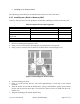
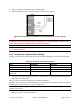
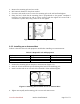
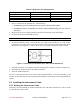
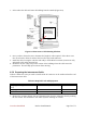
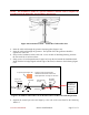
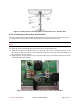
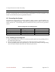
Table Of Contents
- Preface
- PLEASE READ THESE SAFETY PRECAUTIONS!
- Table of Contents
- List of Figures
- List of Tables
- AB-Access Product Overview
- Getting Started
- Base Station Installation
- Access Point Installation
- AB-Extender Installation
- Subscriber Unit Installation
- Indoor Junction Box
- Glossary
- Acronyms/Abbreviations

Axxcelera Broadband Product Install Manual Page 55 of 71
Table 6-5 Required Tools and Equipment
Tools Required Equipment Required Quantity
Phillips-head screwdriver Screws 2
Flat head screwdriver Wallboard inserts 2
Power drill 1
1/8 inch drill bit 1
1. Select a location for the junction box. This should be:
• Somewhere you can easily connect to your PC and a power outlet.
• Somewhere that is accessible for service and troubleshooting (not too close to
the floor).
2. Remove the two screws which attach the junction box faceplate to the wall mount.
3. Set aside the faceplate with PCB and jack.
Attention! Be careful not to damage the two LEDs when removing the PCB.
4. On the Wall Mount portion of the Wall Box, use a flat head screwdriver, or a pair of thin-
nosed pliers, to break out the pre-scored section of casing wall along the bottom edge of the
junction box (see Figure 6-7). This is where later on you will route the interconnect cable.
Figure 6-7 Junction Box Wall Mount (Face Plate and PCB Removed)
5. Using the wall plate as a template, mark the mounting hole locations, as shown in Figure 6-7.
6. Drill 1/8 inch diameter holes at the marked locations.
7. Insert the wallboard inserts.
For now, set the junction box to one side, leaving it disassembled. You will reassemble it and
mount it on the wall when you have prepared and routed the interconnect cable and grounded the
system.
6.5 Installing the Interconnect Cable
6.5.1 Routing the Interconnect Cable
Now that you have installed the outdoor Subscriber Unit and indoor junction box, you are ready
to route the interconnect cable.