
Install Manual
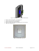
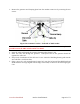
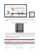
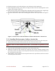
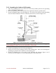
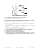
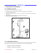
Table Of Contents
- Preface
- PLEASE READ THESE SAFETY PRECAUTIONS!
- Table of Contents
- List of Figures
- List of Tables
- AB-Access Product Overview
- Getting Started
- Base Station Installation
- Access Point Installation
- AB-Extender Installation
- Subscriber Unit Installation
- Indoor Junction Box
- Glossary
- Acronyms/Abbreviations

Axxcelera Broadband Product Install Manual Page 44 of 71
Grommet
Grommet
clamping
plate
Note direction
of taper
Insert wire
into channels
1/2"
3/8"
Shielding
Pin 1
Tab on
underside
1" square tinned copper foil - wrap the copper foil around the
shield/braid and sheath with the left
edge aligned with the edge of the braid.
Figure 5-10 Outdoor Transceiver End of the Interconnect Cable with Cable Preparation
6. Separate the twisted pair wires and align by color code in the order listed in the following
Table 5-3.
Table 5-3 Cable Legend for Interconnect Cable
Pin Color Code
1 White / Orange
2 Orange
3 White / Green
4 Blue
5 White / Blue
6 Green
7 White / Brown
8 Brown
7. Using pin 1 as a reference, insert the individual wires into the channels of the RJ-45
connector. Each wire should penetrate the channels until flush with the connector end. The
copper foil tape should extend past the casing of the RJ-45 connector by approximately ½
inch.
8. When all wires are inserted into the channels in their correct order, use the crimping tool to
permanently crimp the wires to the connector.
Attention! Carefully read the instructions for the crimping tool you are using. Use the
correct crimping tool for the RJ-45 connector you are using. Incorrect installation of the
RJ-45 connector may result in a bad connection between the outdoor transceiver and the
indoor junction box.
9. Insert the RJ-45 connector into the receptacle located underneath the outdoor EX. Make sure
that the connector tab engages the slot in the receptacle.
Grommet is
conductive
and used to
complete
the ground