
Install Manual
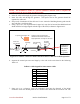
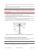
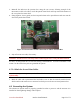
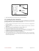
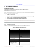
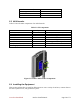
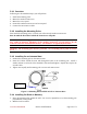
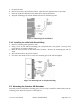
Table Of Contents
- Preface
- PLEASE READ THESE SAFETY PRECAUTIONS!
- Table of Contents
- List of Figures
- List of Tables
- AB-Access Product Overview
- Getting Started
- Base Station Installation
- Access Point Installation
- AB-Extender Installation
- Subscriber Unit Installation
- Indoor Junction Box
- Glossary
- Acronyms/Abbreviations

Axxcelera Broadband Product Install Manual Page 31 of 71
NOTE: The Grommet is made of a special conductive material used to complete the
ground between the Access Point and Access Panel.
2. Insert the cable end through the grommet clamping plate (Figure 4-10)
3. Insert the cable end through the grommet. The tapered end of the grommet should be
opposite the cable end.
4. Strip 1 inch of insulation off the cable end. Leave 3/8 inch of shielding showing and trim the
wire ends flat ½ inch from there.
5. Using a piece of 1 inch squared tinned copper foil, wrap the foil around the shield/braid and
sheath with the left edge aligned with the edge of the braid, as shown in Figures 4-11.
Grommet
Grommet
clamping
plate
Note direction
of taper
Insert wire
into channels
1/2"
3/8"
Shielding
Pin 1
Tab on
underside
1" square tinned copper foil - wrap the copper foil around the
shield/braid and sheath with the left
edge aligned with the edge of the braid.
Figure 4-11 Outdoor Transceiver End of the Interconnect Cable with Cable Preparation
6. Separate the twisted pair wires and align by color code in the order listed in the following
Table 4-3.
Table 4-3 Cable Legend for Interconnect Cable
Pin Color Code
1 White / Orange
2 Orange
3 White / Green
4 Blue
5 White / Blue
6 Green
7 White / Brown
8 Brown
7. Using pin 1 as a reference, insert the individual wires into the channels of the RJ-45
connector. Each wire should penetrate the channels until flush with the connector end. The
Grommet is
conductive
and used to
complete
the ground