PRODUCT INSTALLATION MANUAL for Subscriber Units, Base Stations, Access Points and AB-Extender Units Issue 5.
Preface AB-Access™ System technology enables high-speed, broadband Internet access for fast data transmission, full streaming video, real-time video conferencing, and web surfing. Axxcelera Broadband’s wireless point-to-multipoint and point-to-point solutions (AB-Extender) for fixed networks enables our customers to easily leap-over existing infrastructure, making the initial investment significantly lower than that required for wired alternatives.
Notice While every reasonable effort has been made to ensure the accuracy of this manual, product improvements may result in minor differences between the manual and the product shipped to you. If you have any questions or need an exact specification for a product, please contact Axxcelera Broadband’s Customer Service Team at support@axxcelera.
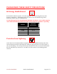
PLEASE READ THESE SAFETY PRECAUTIONS! RF Energy Health Hazard Professional installation required. The radio equipment described in this guide uses radio frequency transmitters. Although the power level is low, the concentrated energy from a directional antenna may pose a health hazard. Use the following chart for determining the minimum safe distance. Do not allow people to come within the minimum safe distance of the antenna while the transmitter is operating.
FCC Notice, USA The AB-Access units comply with Part 15 of the FCC rules. Operation is subject to the following three conditions: • • • This device may not cause harmful interference. This device must accept any interference received including interference that may cause undesired operation. Units with support for an external antenna must be professionally installed. This device is specifically designed to be used under Part 15, Subpart E of the FCC Rules and Regulations.
Table of Contents Preface....................................................................................................................................... 2 PLEASE READ THESE SAFETY PRECAUTIONS!........................ 4 Table of Contents ......................................................................................................... 6 List of Figures ................................................................................................................. 9 List of Tables ...........
4.5.1 Installing the Access Panel ................................................................................... 30 4.5.2 Installing the Interconnect Cables......................................................................... 30 4.5.2.1 Route the Cables ............................................................................................... 30 4.5.2.2 Install the Interconnect Cables (Transceiver End)............................................ 30 4.5.2.
6.6.2 Grounding the Outdoor Subscriber Unit............................................................... 61 6.6.3 Grounding the Indoor Junction Box ..................................................................... 62 6.6.4 Assembling and Mounting the Junction Box........................................................ 63 7 Indoor Junction Box.............................................................................................................. 64 7.1 ATM Cross-Over Cable........................
List of Figures Figure 1-1 AB-Access Typical Deployment................................................................................. 13 Figure 1-2 AB-Access Typical Network Architecture ................................................................. 13 Figure 2-1 Outdoor Subscriber Unit Components ........................................................................ 17 Figure 2-2 Access Point Locations ...............................................................................................
Figure 6-5 Mounting Pole Installed on Pole or Antenna Mast ..................................................... 53 Figure 6-6 Outdoor Subscriber Unit Mounted on Wall ................................................................ 54 Figure 6-7 Junction Box Wall Mount (Face Plate and PCB Removed) ....................................... 55 Figure 6-8 Interconnect Cable Routing Solutions ........................................................................
List of Tables Table 2-1 Required Tools and Extra Equipment .......................................................................... 16 Table 2-2 Packing List .................................................................................................................. 17 Table 4-1 Required Tools and Equipment .................................................................................... 24 Table 4-2 AP Components...................................................................................
Section 1 1 AB-Access Product Overview 1.1 AB-Access System The Axxcelera Broadband AB-Access System is a broadband, fixed, wireless access network for Internet, data, video, and voice applications. AB-Access can enhance or replace existing networks, wired or wireless, or be used to develop new networks.
Figure 1-1 AB-Access Typical Deployment Typically 6 Access Points per Base Station Base Station Subscriber Unit Up to 254 SU per AP Access Point Subscriber Unit Access Point Access Point Eth WAN NOC Router Eth Switch Figure 1-2 AB-Access Typical Network Architecture 1.3.2 Base Station Function The Base Station enables wireless communications between the Subscriber Units and the Wide Area Network (WAN).
• Termination Point and Lightning Arrestor • 48 VDC Power Supply • Uninterruptible Power Supply (UPS) (optional). 1.3.3 Subscriber Unit Function The Subscriber Unit is an integrated device that mounts externally at the customer site. This device provides either ATM or Ethernet communications via the 25Mbps ATM wireless connection with the Base Station. Subscriber Unit elements may include: • Internal Junction Box • Cabling. • Switch, hub or router 1.3.
Section 2 2 Getting Started 2.1 Skills Required The AB-Access Product Installation procedures require some construction-related experience using both power and hand tools. Answer the following questions to determine whether you have the skills to attempt the installation. • Are you comfortable working at heights? • (The installation may require you to climb a ladder and work at heights depending on where you need to install your outdoor transceiver.
2.3 Required Tools and Equipment This section lists all the extra tools and equipment mentioned in this guide that you will need to perform the installation. None of the items listed in Table 2-1 are supplied with the kit, so make sure you gather everything you need before you start. Use the table below to check exactly what you will need (this will depend on where you are going to install the outdoor transceiver).
Figure 2-1 Outdoor Subscriber Unit Components Table 2-2 Packing List Item Outdoor Subscriber Unit Mounting pole Pole clamp M6 washer M3 x M10 machine thread screws Power supply Power cord Indoor junction box Quantity 1 1 1 2 2 1 1 1 Notes See item 1 in Figure 2-1 See item 2 in Figure 2-1 See item 3 in Figure 2-1 See item 4 in Figure 2-1 See item 5 in Figure 2-1 2.5 Performing a Site Survey This section explains how to select the best location for mounting the outdoor transceiver.
• Area map with an accurate direction legend showing magnetic north. • Access Point locations – these should be provided by your service provider. 2.5.2 Access Point Locations If you are installing the unit without the aid of a qualified installer, you need to determine the general direction of any Access Points from your house or building. You may be able to ‘see’ several APs, depending on your coverage area. Attention! The following method uses a compass to find the bearing of any APs from your site.
Figure 2-3 Aligning the Compass and Map 7. Write down the directions (compass bearings) of your Access Points. For example, in Figure 2-3, Access Point A is located northwest of the building and Access Point B is located between north and northeast. (If you can be more accurate than this, you will get better reception when you install your outdoor transceiver.) 2.5.
Figure 2-4 Selecting an Access Point You should mount your outdoor Subscriber Unit as high as possible on your building, and align it to the compass reading you have just taken. For example, the previous Figure 2-4 shows the path to Access Point A obstructed by a cluster of trees. However, there are two possible mounting locations for the outdoor Subscriber Unit giving a clear line of sight to Access Point B. Attention! Your outdoor transceiver has a beam width of approximately 20 degrees.
Follow the same instructions for aligning and locating the AB-Extender units as for the standard AP and SU. Note: the difference in beam width will make alignment more difficult but has the advantage of lower susceptibility to interference.
Section 3 3 Base Station Installation 3.1 System Overview This section briefly describes the AB-Access hardware and software system components that comprise a Base Station. Figure 3-1 Base Station Overview 3.
A Base Station can have up to six Access Points. Each AP consists of an outdoor transceiver (which contains the antenna and associated electronics that transmit and receive broadband wireless signals to and from Subscriber Units) and an indoor wallbox or access panel. 3.3 AB-Extender Units A Base Station may have a number of AB-Extender units. Each EX consists of an outdoor transceiver and an indoor wallbox or access panel. 3.
Section 4 4 Access Point Installation 4.1 Before You Start This section lists the information needed to install an AP. 4.2 Information Required Before you perform the installation, a site survey should have been performed by the service provider. From this, you will need to know: • Number of APs to install • Where the outdoor transceivers will be mounted (antenna mast, pole or building) • Heights at which the outdoor transceivers will be mounted.
Power drill 1/8 inch drill bit ¼ inch masonry drill bit Cable clips Anchor sleeves RJ-45 connectors bodied) (plastic 3/16 inch hex (Allen) wrench or 10 mm Bubble level or plumb line Adjustable wrench Wire snake (if routing cable through interior walls) Crimping tool (must be specifically matched for the RJ-45 connector used) Wire stripper Small wire cutters Punch down tool 4.3 Access Points Table 4-2 lists the main components of an Access Point.
Figure 4-2 Outdoor Access Point Components 4.4 Installing the Equipment This section explains how to install an AP transceiver onto a variety of surfaces, connect them to the indoor junction box, and ground the system. The most likely scenario is to install six transceivers on a single tower or mast 60 degrees apart. 4.4.1 Overview Following are the installation steps you will perform: 1. 2. 3. 4. 5. Install the mounting poles. Mount the outdoor transceivers. Mount the access panel.
4.4.3 Installing On an Antenna Mast 1. Position the mounting pole on the antenna mast. 2. Insert the U-bolts around the mast and through the holes in the mounting pole. Install a washer and nut to each side of the threaded U-bolt and hand tighten. Repeat this step for the second U-bolt. 3. Tighten nuts equally until mounting pole is secure and cannot rotate. Typically 2 ½ inch Figure 4-3 Mounting Pole Installed on Pole or Antenna Mast 4.4.4 Installing On Brick or Masonry 1.
2. Using a level, be sure that the mounting pole is perpendicular to the ground. You may need to use spacers, as shown in Figure 4-5. 3. Mark the hole locations for the drilled hole locations. Remove the mounting pole and set aside. 4. Drill 1/8-inch holes in the places marked. 5. Use #10 or #12 wood screws to secure the mounting pole to the wall and tighten. Figure 4-5 Mounting Pole on Clapboard Siding 4.
5. Tighten the mounting screws.
4.5.1 Installing the Access Panel You will probably install the Access Panel in a rack, along with the anchor switch and other associated equipment. However, keep in mind that the access panel should be: • Located where you can easily connect to a power supply. • Close to the anchor switch. • Accessible for service and troubleshooting. • Protected from rain and extremes of temperature (it is designed for indoor use). 4.5.
NOTE: The Grommet is made of a special conductive material used to complete the ground between the Access Point and Access Panel. 2. Insert the cable end through the grommet clamping plate (Figure 4-10) 3. Insert the cable end through the grommet. The tapered end of the grommet should be opposite the cable end. 4. Strip 1 inch of insulation off the cable end. Leave 3/8 inch of shielding showing and trim the wire ends flat ½ inch from there. 5.
copper foil tape should extend past the casing of the RJ-45 connector by approximately ½ inch. 8. When all wires are inserted into the channels in their correct order, use the crimping tool to permanently crimp the wires to the connector. Attention! Carefully read the instructions for the crimping tool you are using. Use the correct crimping tool for the RJ-45 connector you are using.
3. Reinstall the PCB into the junction box using the two screws, allowing enough of the interconnect cable to be able to reach the punch down block and wrap around the mounts of the cover plate for strain relief. 4. Using Figure 4-13 as a guide, use the 110 punch down tool to punch down each wire into the slot on the punch down block. Figure 4-13 Interconnect Cable Connections to Indoor Junction Box 5. Snip off excess wire ends, if necessary.
1. Grounding all the outdoor transceivers as shown in Figure 4-12. 2. Grounding the Access Panel to the rack. 4.6.1 Grounding the Outdoor Access Points 1. Place the grounding rod so as to allow for the shortest possible path from the grounding cable to the outdoor Access Points. 2. Drive the grounding rod into the ground at least eight inches from the ground surface. 3. Attach a grounding clamp to the grounding rod.
Figure 4-15 Mounting Pole with Ground Lug 7. Install a grounding wire from the junction box to the grounding rod. 4.6.2 Grounding the Indoor Junction Box To ground the indoor junction box, you will need to install a grounding wire from the junction box to the grounding rod. The wire should be long enough to reach from the junction box to the grounding rod with 3 to 6 extra feet to allow for strain relief. 1.
Indoor Junction Box Ground Connection Figure 4-16 Indoor Junction Box Ground Connection 4.6.3 Assembling and Mounting the Junction Box 1. Place the junction box wall mount over the drilled holes. 2. Insert the screws and tighten. 3. Reinstall the faceplate onto the junction box using the two screws.
Section 5 5 AB-Extender Installation 5.1 Before You Start This section lists the information you will need to install an AB-Extender unit. 5.2 Information Required Before you perform the installation, a site survey should have been performed by the service provider. From this, you will need to know: • Number of EXs to install • Where the outdoor transceivers will be mounted (antenna mast, pole or building) • Heights at which the outdoor transceivers will be mounted.
RJ-45 connector used) Wire stripper Small wire cutters Punch down tool 5.3 AB-Extender Table 5-2 lists the main components of an AB-Extender.
5.4.1 Overview Following are the installation steps you will perform: 1. 2. 3. 4. 5. Install the mounting poles. Mount the outdoor transceivers. Mount the access panel. Ground the outdoor transceivers and access panel Connect the interconnect cables. 5.4.2 Installing the Mounting Poles First install the mounting poles, on which you will mount the outdoor transceivers. Bear in mind the direction in which the transceivers will point. Attention! The mounting pole must be mounted in a vertical position.
3. 4. 5. 6. Set the pole aside. Drill ¼ inch holes at the marked locations. Drill the holes approximately ½ inch deep. Insert the expansion shields into the drilled holes and tap them home. Align the mounting pole with the drilled holes and fix with the lag bolts. Figure 5-3 Mounting Pole Installation 5.4.5 Installing On a Wall with Wood Siding 1. Place the mounting plate against the wall. 2. Using a level, be sure that the mounting pole is perpendicular to the ground.
Figure 5-5 Mounting Parts for an Outdoor AB-Extender 1. 2. 3. 4. 5. Place the outdoor AB-Extender on the mounting pole. Align the pole clamp with the mounting holes. Insert the mounting screws and hand tighten. Rotate the outdoor AB-Extender so it is pointing in the correct direction. Tighten the mounting screws.
Figure 5-7 Tilt Bracket Figure 5-8 AB-Extender with Mounted Tilt Bracket 5.5.1 Installing the Interconnect Cables For each interconnect cable, you will need to perform the following steps. 5.5.1.1 Route the Cables 1. Select where the cable will enter the building from the outside. 2. Determine the length of cable required. Allow three extra feet on each end to allow for strain relief, as well as any bends and turns. 3. Route the cable. 5.5.1.
1. Remove the grommet and clamping plate from the outdoor transceiver by removing the two screws. Figure 5-9 Grommet Location - Underside of AB-Extender NOTE: The Grommet is made of a special conductive material used to complete the ground between the AB-Extender and Access Panel. 2. Insert the cable end through the grommet clamping plate (Figure 5-10) 3. Insert the cable end through the grommet. The tapered end of the grommet should be opposite the cable end. 4.
1" square tinned copper foil - wrap the copper foil around the shield/braid and sheath with the left edge aligned with the edge of the braid. Insert wire into channels Tab on underside Shielding 3/8" Pin 1 Note direction of taper Grommet clamping plate Grommet 1/2" Grommet is conductive and used to complete the ground Figure 5-10 Outdoor Transceiver End of the Interconnect Cable with Cable Preparation 6.
10. Slide the grommet up the cable and press it into the bottom of the outdoor EX. 11. Slide the grommet clamp up the cable and align the holes with the mounting holes on the bottom of the outdoor transceiver. 12. Insert the two screws in the mounting holes and tighten until the grommet has a slight bulge. Be sure to tighten both screws equally so that the grommet is seated correctly. 13. Secure the interconnect cable to the mounting pole with the cable clip as shown in Figure 511.
Figure 5-12 Interconnect Cable Connections to Indoor Junction Box 10. Snip off excess wire ends, if necessary. Attention! Avoid excessive wire loops when connecting the wire to the punch down block. For now, set the junction box to one side leaving it disassembled. You will reassemble it and mount it on the wall when you have grounded the system. 5.5.1.4 Mark the AB-Extender Cables Attention! Step 1 is important, and will enable the network installer to configure the system easily. 1.
5.6.1 Grounding the Outdoor AB-Extender 1. Place the grounding rod so as to allow for the shortest possible path from the grounding cable to the outdoor AB-Extender. 2. Drive the grounding rod into the ground at least eight inches from the ground surface. 3. Attach a grounding clamp to the grounding rod. You will use this clamp to attach grounding wires for both the outdoor transceiver and indoor junction box, reference Figure 5-13.
Figure 5-14 Mounting Pole with Ground Lug 7. Install a grounding wire from the junction box to the grounding rod. 5.6.2 Grounding the Indoor Junction Box To ground the indoor junction box, you will need to install a grounding wire from the junction box to the grounding rod. The wire should be long enough to reach from the junction box to the grounding rod with 3 to 6 extra feet to allow for strain relief. 9.
Indoor Junction Box Ground Connection Figure 5-15 Indoor Junction Box Ground Connection 5.6.3 Assembling and Mounting the Junction Box 4. Place the junction box wall mount over the drilled holes. 5. Insert the screws and tighten. 6. Reinstall the faceplate onto the junction box using the two screws.
Section 6 6 Subscriber Unit Installation 6.1 Installation Overview The Subscriber Unit installation steps are as follows: 1. Install the mounting pole and mount the outdoor Subscriber Unit (see Figure 6-1). 2. Install the indoor junction box. 3. Route the interconnect cable. Connect it to the outdoor Subscriber Unit and the indoor junction box. 4. Ground both the outdoor Subscriber Unit and indoor junction box. 5. Perform initial startup and testing.
• Installing on an Antenna Mast The following sections describe the installation procedure for each of the above. 6.2.1 Installing on a Brick or Masonry Wall Table 6-1 describes the tools and equipment needed when installing on a brick or masonry wall.
8. Insert a lag bolt in each of the holes and hand tighten. 9. Tighten all lag bolts with a wrench, being careful not to over tighten. Figure 6-3 Mounting Pole Installation Using Expansion Sleeves and Lag Bolts Attention! The mounting pole must be mounted in a vertical position. Failure to do so may result in improper alignment of the outdoor transceiver. IMPORTANT – Before you install the SU, be sure to record the MAC address found on the SU for future reference. 6.2.
3. 4. 5. 6. Remove the mounting pole and set it aside. Drill 1/8 inch diameter in the places marked. Use #10 or #12 wood screws to secure the mounting pole to the wall and hand tighten. Using the level, check that the mounting plate is perpendicular to the ground. Readjust if necessary (you might need to add or remove spacers) and then tighten all screws with a screwdriver or power drill, being careful not to over tighten. Figure 6-4 Mounting Pole on Clapboard Siding 6.2.
Attention! The mounting pole must be mounted in a vertical position. Failure to do so may result in improper alignment of the outdoor transceiver. Warning! The mounting pole must be grounded. See Grounding the System in Section 6.6. 6.3 Installing the Outdoor Subscriber Unit Now that you have installed the mounting pole, you are now ready to install the outdoor Subscriber Unit (SU) to the mounting pole. Table 6-4 describes the tools and equipment needed to install the SU.
Table 6-5 Required Tools and Equipment Tools Required Phillips-head screwdriver Flat head screwdriver Power drill 1/8 inch drill bit Equipment Required Screws Wallboard inserts Quantity 2 2 1 1 1. Select a location for the junction box. This should be: • Somewhere you can easily connect to your PC and a power outlet. • Somewhere that is accessible for service and troubleshooting (not too close to the floor). 2. Remove the two screws which attach the junction box faceplate to the wall mount. 3.
1. Select where the cable will enter the building from the outside (Figure 6-8). NOTE - Add a drip loop at wall penetration to prevent water from entering Figure 6-8 Interconnect Cable Routing Solutions 2. Once you have chosen the route, determine the length of cable required. Allow three extra feet on each end to allow for strain relief as well as any bends and turns. 3.
NOTE: The Grommet is made of a special conductive material used to complete the ground between the Subscriber Unit and indoor junction box. Figure 6-9 Grommet Location -- Underside of Subscriber Unit 2. Insert the cable end through the grommet clamping plate (Figure 6-10). 3. Insert the cable end through the grommet. The tapered end of the grommet should be opposite the cable end. 4. Strip 1 inch of insulation off the cable end.
Table 6-7 Cable Legend for Interconnect Cable Pin 1 2 3 4 5 6 7 8 Color Code White / Orange Orange White / Green Blue White / Blue Green White / Brown Brown 7. Using pin 1 as a reference, insert the individual wires into the channels of the RJ-45 connector. Each wire should penetrate the channels until flush with the connector end. The copper foil tape should extend past the casing of the RJ-45 connector by approximately ½ inch. 8.
Figure 6-11 Interconnect Cable Installation to Subscriber Unit -- Bottom View 6.5.4 Connecting to the Indoor Junction Box Note that the junction box should still be disassembled and not screwed to the wall at this point. 11. Strip 2 inches of insulation off the junction box end of the interconnect cable. Attention! Don’t cut off the shield from the cable – you will need it to ground the system later. 12. Insert the cable end through the notched out section of the junction box. 13.
15. Snip off excess wire ends, if necessary. Attention! Avoid excessive wire loops when connecting the wire to the punch down block. For now, set the junction box to one side leaving it disassembled. You will reassemble it and mount it on the wall when you have grounded the system. 6.6 Grounding the System The AB-Access System must be properly grounded in order to protect it and the building it is installed on from lightning damage.
Indoor wall box Outdoor transceiver Grounding cable (10 AWG) Grounding cable (10 AWG) 6 AWG Premises electrical ground Clamp Grounding rod Concrete foundation Figure 6-13 Ground Connections for Subscriber Unit 6.6.2 Grounding the Outdoor Subscriber Unit 1. To ground the outdoor Subscriber Unit, you will need to install a grounding wire from the mounting pole to the grounding rod.
Figure 6-14 Mounting Pole with Ground Lug 6.6.3 Grounding the Indoor Junction Box To ground the indoor junction box, you will need to install a grounding wire from the junction box to the grounding rod. The wire should be long enough to reach from the junction box to the grounding rod with 3 to 6 extra feet to allow for strain relief. 17. Feed the grounding cable through the broken out section of the wall cover (alongside the interconnect cable). 18.
Indoor Junction Box Ground Connection Figure 6-15 Indoor Junction Box Ground Connection 6.6.4 Assembling and Mounting the Junction Box 7. Place the junction box wall mount over the drilled holes. 8. Insert the screws and tighten. 9. Reinstall the faceplate onto the junction box using the two screws.
Section 7 7 Indoor Junction Box The indoor junction box/wall box consists of a PCB that inserts power into the CAT-5 cable and provides secondary lightening protection. Photos of the indoor Junction Box are shown in Figures 7-1 and 7-2.
The indoor junction box can be wired for ATM25 or Ethernet interfaces. Note that the PCBs may be housed in separate plastic boxes or mounted in a card cage. Table 7-1 describes the cable legend to follow. Table 7-1 Cable Legend - Junction Box Interconnect Cable Pin 1 2 3 4 5 6 7 8 Signal Transmit High (+) Transmit Low (-) LED2 Supply Minus Supply Plus LED1 Receive High (+) Receive Low (-) Color Code White / Orange Orange White / Green Blue White / Blue Green White / Brown Brown 7.
Glossary TERM DEFINED Access Point An Access Point (AP) is a component of a Base Station (BS) that contains the antenna used to communicate with a Subscriber Unit (SU). The Anchor Switch (AS) is an ATM access switch that is a component of a Base Station (BS). A device for transmitting and/or receiving radio waves. A data transmission method in which data may be sent at irregular intervals (without reference to clock signals).
TERM DEFINED Element Management System The Element Management System (EMS), located on a workstation at an appropriate point in the network, allows you to configure, control, and monitor all components of the AB-Access System. Management information base allows external management system access. A multiplexer is device or system capable of combining elementary streams into one aggregate transport stream. A network is an interconnection of computer systems, terminals, or data communications facilities.
TERM DEFINED A transmitter is an electronic device, consisting of oscillator, modulator, and other circuits, that produce a radio or television electromagnetic wave signal for radiation into the atmosphere by an antenna. Service that operates on a connection basis and allows for raw Unspecified Bit cell or best effort transport by the network. In this service, cells Rate are transported by the network whenever bandwidth is available and traffic is presented by the user.
Acronyms/Abbreviations The following is a list of acronyms and abbreviations associated with the AB-Access System, some of which may appear in this guide.
ACRONYM DEFINED Federal Communications Commission FCC Frequency Division Duplex FDD Fault and Performance Management System FPMS Gigabits per second Gbps Generic Flow Control GFC Gigahertz GHz Graphical User Interface GUI In Phase and Quadrature I&Q Internet Engineering Task Force IETF Intermediate Frequency IF Internet Protocol IP Inter-Symbol Interference ISI Instructional Television Fixed Service ITFS kilobits per second Kbps Local Area Network LAN Logical Link Control LLC Line of Sight LOS Media Access
ACRONYM DEFINED RT-VBR Real Time Variable Bit Rate Receiver RX Segmentation And Reassembly SAR Small Computer System Interface SCSI Simple Network Management Protocol SNMP Signal to Noise Ratio SNR Small Office/Home Office SO/HO Synchronous Optical Network SONET Shielded Twisted Pair STP Subscriber Unit SU Subscriber Unit Management Protocol SUMP Switched Virtual Circuit SVC 1.