
User manual


97
Fig. 4.9.2.3. Primed burst stimulation for LTP induction consisting of a single pulse on one digital output
(D2), and a single train on another digital output (S0) which then go to trigger the same Stimulus Isolation
Unit by using an OR chip or two diodes.
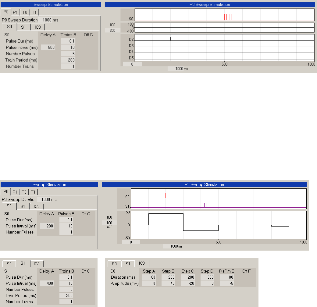
Fig. 4.9.2.4 shows how intracellular stimulation can be coincident with extracellular pulse and train
stimulation. In this example S0, S1 and Intracellular with RsRm stimulation are On. In this example an
intracellular depolarization occurs during the one priming S0 pulse, and hyperpolarization occurs during
the S1 train. Intracellular voltage changes could have interesting effects on the ability of extracellular
pulses and trains to induce LTP or LTD.
Fig. 4.9.2.4. Extracellular heterosynaptic primed burst stimulation (S0 single pulse, S1 train) and
coincident intracellular (IC) depolarization and hyperpolarization stimulation with an RsRm test pulse.
It is important to understand that what you see in the Train and Pulse Stimulation graphs is what stimulus
pulses you will generate. If not all of your stimulus pulses ‘fit’ in the stimulation graphs, they will not be
generated and no error message will be produced to tell you that. It is up to you to see that this does not
occur.
Analog stimulation now has the capability of producing ramps that were generated within Train1 Loop
(Fig. 4.9.2.5).