
User manual


94
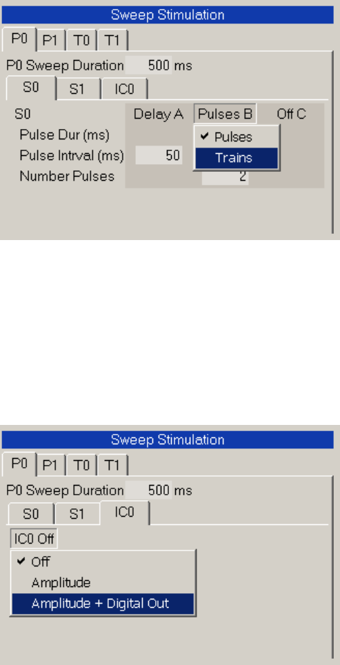
Fig. 4.9.1.3. Setting S0 output to ‘Pulses’ or ‘Trains’ by clicking on the Pulses/TrainsB Label/Button that
raises up when the mouse cursor is moved over it.
IC0 stimulation can be either ‘Off’, ‘Amplitude’ On, or ‘Amplitude + Digital Out’ On as set by the pop-up
menu that pops up when the mouse cursor is clicked on the S0 or S1 Label/Button in the S0 or S1
tabsheet (Fig. 4.9.1.4).
Fig. 4.9.1.4. Setting Intracellular Epoch output to ‘Off’, Analog Out ‘Amplitude’ On, or Analog Out
‘Amplitude + Digital Out’ On, by clicking on the IC0 Label/Button that raises up when the mouse cursor is
moved over it.
If IC0 Analog Out ‘Amplitude’ or ‘Amplitude + Digital Out’ stimulation is On, the output for each Epoch0 to
Epoch19 in P0, P1, T0, or T1 Sweeps can be either:
1) Off
2) Step
3) RsRm Step
4) Ramp
5) Begin Loop
6) End Loop
which is set by changing Eoch1 through Epoch18 (Fig. 4.9.1.5). The RsRm Step is the step where patch
electrode series resistance and cell input resistance are measured relative to the previous step.