
User manual


92
4.9 Choosing Pulse/Train Sweep Stimulation Protocols and
Setting Stimulation Values
The complete stimulation output of WinLTP is a combination of the output of the P0, P1, T0 and
T1sweeps in the Protocol Builder (Chapters 7, 8 and 10) plus the Evoked Single and Repeat Sweeps.
4.9.1 Choosing the Sweep Stimulation Protocol
The extracellular, intracellular and digital stimulation in each sweep is controlled by the fields in the P0,
P1, T0 or T1 tabsheet in the Sweep Stimulation area (Fig. 4.9.1.1, also see Section 3.1.3 and Figs.
3.1.3.1, 3.1.3.2 and 3.1.3.3).
The stimulations that can be controlled by the Sweep Stimulation area include:
1) Sweep Duration
2) S0 and S1 extracellular stimulation (organized in terms of pulses and trains)
3) IntraCellular (IC) Analog Output stimulation organized as epochs (e.g. up to 6 sequential pulses,
PulseA to PulseE)
4) Four Digital Outputs that can also be produced during the Intracellular (IC) epochs.
To set the sweep stimulation protocol, first choose the desired sweep by clicking on the P0, P1, T0 or T1
tabsheet in the Sweep Stimulation area.
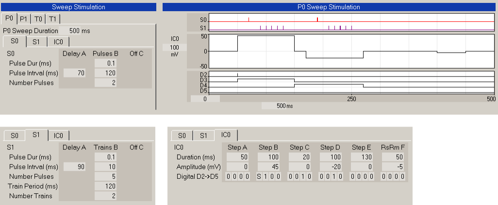
Fig. 4.9.1.1. P0sweep stimulation consisting of two S0 pulses (left side of top panel), two S1 trains (left
bottom panel), and IntraCellular analog output channel 0 (IC0), Digital Sync output (see the ‘S’ in DO2),
and Digital Out step output (see the ‘1’s in DO3 and DO4) (right bottom panel).
As discussed in Section 3.1.3, the Field Sweep Stimulation area is functionally coupled with the Graph
Stimulation area, so that, for example, when you click on the P0 tabsheet in the Field Sweep Stimulation
area, the P0 Sweep Stimulation graph comes up (Fig. 3.1.3.3).