
User manual


91
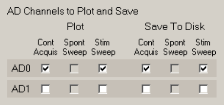
Fig. 4.7.1. AD Channels to Plot and Save Panel.
Then check which AD channels you want to plot for Continuous Acquisition and Stimulation Sweeps, and
which AD channels you want to save to disk for Continuous Acquisition and Stimulation Sweeps. Note
that Plotting and saving to Spontaneous Sweeps is currently disabled.
4.8 Set the Data Acquisition Values
Setting Analog Input values has already been discussed in Section 2.13.1.
4.8.1 Setting Analog Output Values
The lower left panel of the Edit Protocol dialog box and the Acquisition/Stimulation Parameters tabsheet is
the Analog Output Channels panel (see Fig. 2.13.1.1).
This currently sets IC0 output (IC1 not implemented yet). The output can either be in straight volts ‘V’, in
‘mV’ for patch clamp voltage-clamp mode, or ‘nA’ or ‘pA’ for current-clamp mode. It is set in the
DataTypeUnits field.
If the output is in volts, the DataTypeUnit is set to ‘V’, the Gain field is set to ‘1’, and the Units/V field
becomes ‘1 V/V’.
For patch clamp voltage-clamping, the DataTypeUnit is set to ‘mV’, and the Gain and Units/V fields
depend on the output gain of the patch clamp amplifier. For example, with Axon Instruments patch clamp
amplifier 200B, the sensitivity is 20 mV cell voltage to 1 volt input voltage, or 20 mV/V, and the Units/V
field is therefore set to ‘20 mV/V’. The Gain field then becomes ‘50’. This is in fact the default setting.
For current clamping, the DataTypeUnit is set to either ‘nA’ or ‘pA’, and we will set it to ‘nA’ in this
example. For the Axon 200B, the output to the cell in nA is (2/β) nA per volt input, and where β = 1, this
becomes 2 nA/V, and the Units/V field is therefore set to ‘2 nA/V’. The Gain field then becomes
‘500000000’.