
User manual


40
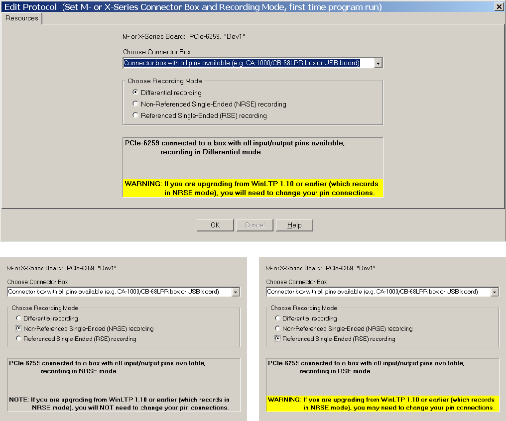
Fig. 2.8.5. The Resources tabsheet in the Edit Protocol (Set M- or X-Series Connector Box and
Recording Mode, first time program run)’ dialog box showing the choice of a connector box with all pins
available such as the CA-1000 enclosure with a CB-68LPR connector block. With the connector box with
all pins available, you can choose between Differential recording mode (top panel) , Non-Referenced
Single-Ended (NRSE) mode (lower left panel), and Referenced Single-Ended (RSE) mode (lower right
panel.
2.9 Calibrate Data Acquisition Board When Running the First Time
If this is the first time WinLTP has been run on this M or X-Series board or this Digidata 132x board, a
‘Calibrate M- or X-Series board’ or ‘Calibrate Digidata 132x’ dialog box will appear. Make sure to remove
the connections to the Analog Outputs before calibrating. To calibrate, simply click on the ‘Calibrate…’
button. Figs. 2.9.1 and 2.9.2 show the calibration results for M or X-Series and Digidata 132x boards after
the ‘Calibrate…’ button has been pressed and calibration has successfully concluded.