
User manual


38
settings or pin-to-pin wire connections that need to be made. The bottom lines (if any) give a WARNING
(in yellow) for any setting need be changed when upgrading from WinLTP 1.10 or earlier.
NOTE: After you have chosen the Connector Box you installed in Section 2.4.3 and have chosen the
Recording Mode, set any switches mentioned in the Information Panel, and any pin-to-pin wire
connections required. This is particularly true if the bottom lines give a WARNING (in yellow) for any
setting need be changed when upgrading from WinLTP 1.10 or earlier.
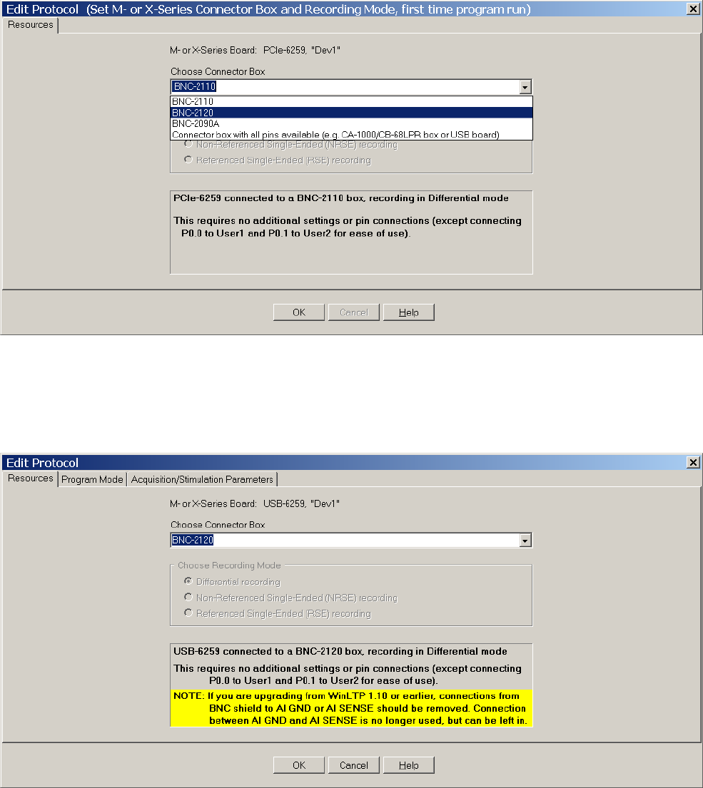
Fig. 2.8.2. The Resources tabsheet in the Edit Protocol (Set M- or X-Series Connector Box and
Recording Mode, first time program run)’ dialog box showing the choices Connector Boxes: BNC-2110,
BNC-2120, BNC-2090A and a Connector Box that has all input/output pins available such as the CA-1000
enclosure with a CB-68LPR connector block. You would also choose ‘Connector box with all pins
available’ to use a USB board.
Fig. 2.8.3. The Resources tabsheet in the Edit Protocol (Set M- or X-Series Connector Box and
Recording Mode, first time program run)’ dialog box showing the choice of a BNC-2120 Connector Box.