
User manual


37
2.8 Choose the Connector Box and Recording Mode for M-,X-
Series boards
If this is the first time WinLTP has been run on this M or X-Series board, an ‘Edit Protocol (Set M- or X-
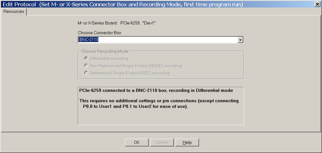
Series Connector Box and Recording Mode, first time program run)’ dialog box will appear (Fig. 2.8.1).
Fig. 2.8.1. The Resources tabsheet in the Edit Protocol (Set M- or X-Series Connector Box and
Recording Mode, first time program run)’ dialog box showing the choice of a BNC-2110 Connector Box.
The top line of the Resources tabsheet of this dialog box shows the National Instruments data aquistion
board you have installed, in this case a PCIe-6259.
The section below that requests you choose from a drop-down list a Connector Box that is connected to
this data acquisition board (Fig. 2.8.2). The current Connector Boxes to choose from include the BNC-
2110, BNC-2120, BNC-2090A and a connector box that has all input/output pins available.
NOTE: Choose the Connector Box you installed in Section 2.4.3.
This is then followed by a ‘Choose Recording Mode’ radiobutton group which is either set to a particular
appropriate value for a particular Connector Box (for example Differential recording from the BNC-2110
Connector Box (Fig. 2.8.1), or the BNC-2210 Connector Box (Fig. 2.8.3). Or for certain Connector Boxes
(such as the BNC-2090A, Fig. 2.8.4) or a connector box that has all input/output pins available (Fig.
2.8.5)) you can choose Differential, Non-Referenced Single-Ended (NRSE), or Referenced Single-Ended
(RSE) recording mode.
Below the ‘Choose Recording Mode’ radiobutton group is an Information Panel. The top line shows the
data acquisition board, connector box and recording mode. The middle lines show any additional switch