
User manual


22
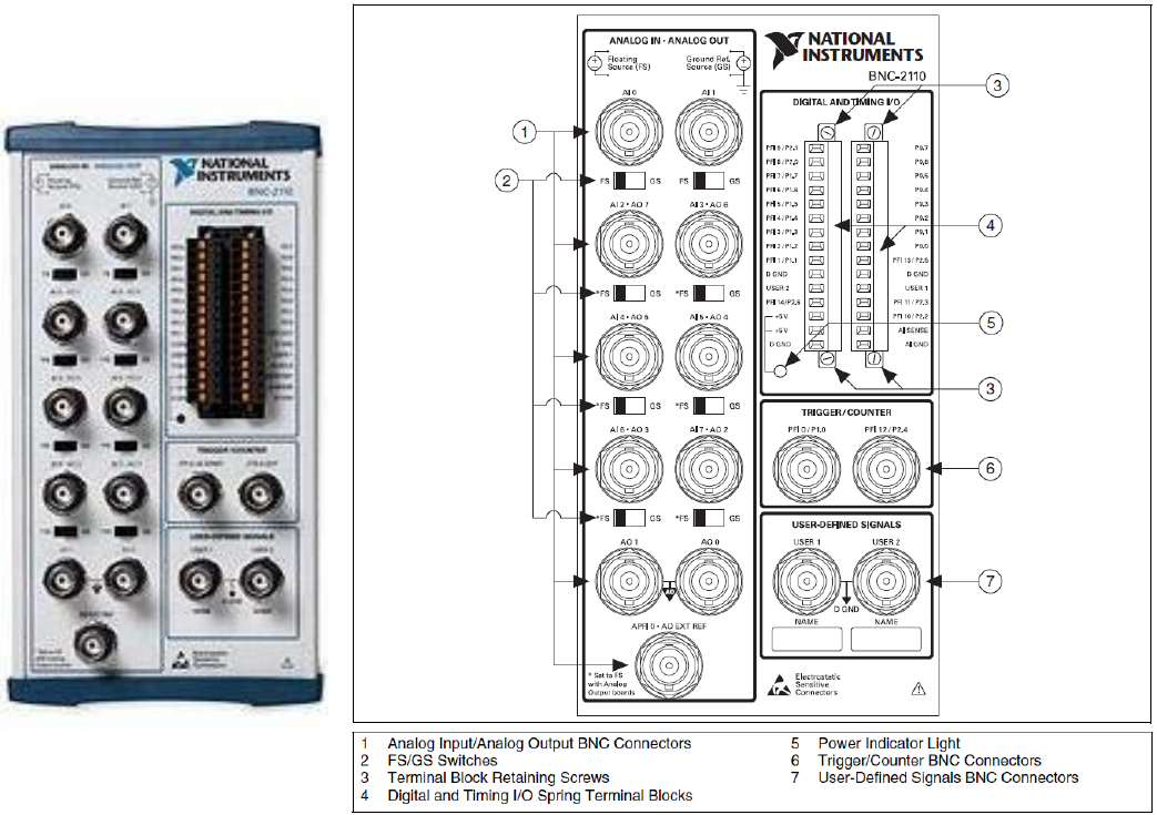
For a Floating Signal (FS) Source such as a signal from a battery powered biological amplifier, switch the
FS/GS switch to FS. For a Ground Signal (GS) Source such as a signal from a mains powered and
grounded biological amplifier, switch the FS/GS switch to GS.
Analog Outputs 0 and 1 are used as normal (plugged into with a shielded BNC cable).
To use the extracellular stimulation outputs, connect a wire from pin P0.0 to User1 (so that the User1
BNC can be S0 output), and connect a wire from pin P0.1 to User2 (so that the User2 BNC can be S1
output).
To use the four Digital Outputs (D2 to D5), directly connect wires to the P0.2 to P0.5, respectively.
Fig. 3.3.1.1. Photograph of the BNC-2110 (left), and the AI (AnalogIn), AO (AnalogOut), and User1 and
User2 BNC connectors, the FS/GS switches for each analog input channel, and the pin connections for 8
high-speed digitial outputs (P0.0 to P0.7) (right). For ease of use, a wire is connected from the P0.0 pin to
the User1 pin, and from P0.1 pin to the User2 pin so that the Stimulus Isolation Unit for signal S0 can be
connected by a BNC cable to User1, and the Stimulus Isolation Unit for signal S1 can be connected by a
BNC cable to User2 (Copyright National Instruments, 2007).