
User manual


214
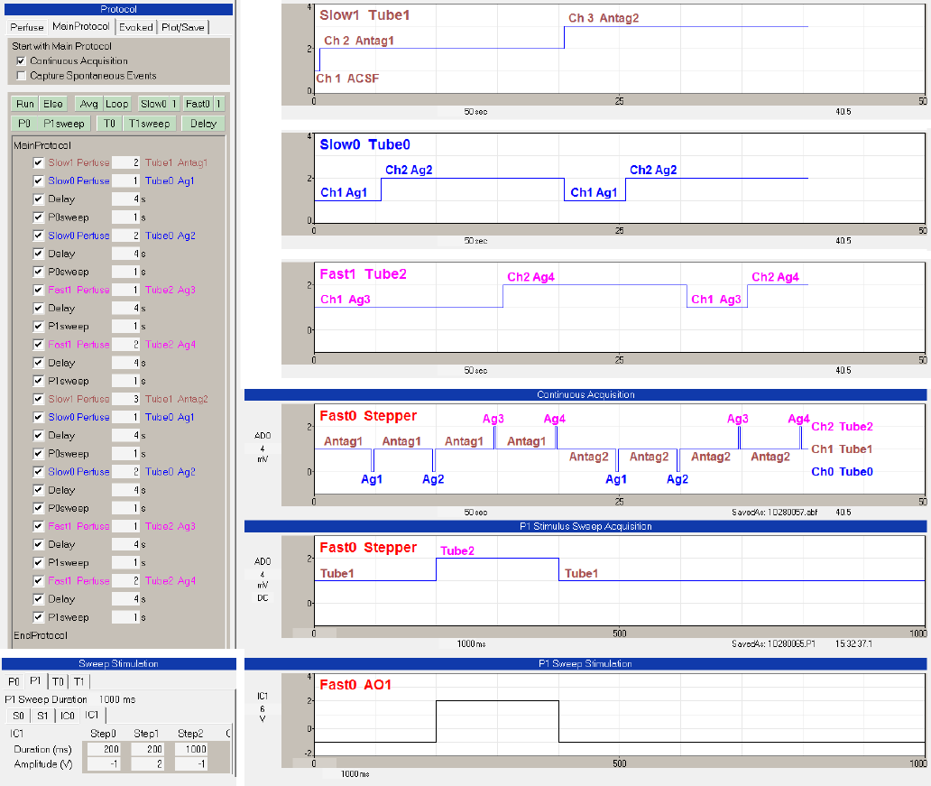
Fig. 10.4.2.4. Running the Triple-Line/Stepper example. The ‘Slow0 Perfuse’, ‘Slow1 Perfuse’ and ‘Fast1
Perfuse’ events in the Protocol Builder (upper left) show when the Slow0/Tube0, Slow1/Tube1 solutions
are changed. The upper right panel shows the Slow1 Tube1 switch from ‘Ch1 ACSF’ to ‘Ch2 Antag1’ to
‘Ch3 Antag2’. The next panel below shows the Slow0 Tube0 switch between ‘Ch1 Ag1’ and ‘Ch2 Ag2’.
The next panel below that shows the Fast1 Tube2 switch between ‘Ch1 Ag3’ and ‘Ch2 Ag4’. The
‘Continuous Acquisition’ and the ‘P0 Stimulus Sweep Acquisition’ panel show recordings of the AO1
voltage shifts temporarily changing from ‘Ch1 Tube1’ to ‘Ch0 Tube0’ or ‘Ch2 Tube2’. This results in the
solutions switching between Antag1, Ag1, Antag1, Ag2, Antag1, Ag3, Antag1, Ag4, then Antag2, Ag1,
Antag2, Ag2, Antag2, Ag3, Antag2, Ag4. The Sweep Stimulation bottom panels show change of AO1 (ie
IC1) voltage output during a P1sweep. The -1V means to take whatever the current Fast0 output is
BETWEEN sweeps (and when the MainProtocol is off), ie 2V or Ch2.