
User manual


213
The Slow0 and Slow1 output to valve controllers is digital and identical to the Dual-Line/Stepper system.
However, which Fast0/Fast1 perfusion output control is high-speed digital using Port0 and which is analog
(using AO1 or AO1+AO2) is determined by the choice made in the Fast0 Perfusion Change radiobutton
group. As shown in Fig. 10.4.2.2A, if the Fast0 output to the stepper is chosen to be high-speed digital
Port0 (in this case 4 bit binary), then the Fast1 output to a valve controller has to be analog (in this case
AO1). As shown in Fig. 10.4.2.2B, if the Fast0 output to the stepper is chosen to be analog (in this case
AO1), then the Fast1 output to a valve controller has to be high-speed digital Port0 (in this case 4 bit
binary).
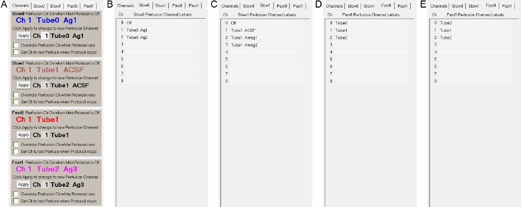
Setting up the perfusion channel label information (Fig. 10.4.2.3, B-E) is similar to that for the Dual-
Line/Stepper system except for the addition of Fast1 perfusion solutions.
For the Fast1 (Tube 2 valve controller), the Fast1 Perfuse event in the Protocol Builder can either output
agonist 3 or agonist 4 (‘Tube2 Ag3’ or ‘Tube2 Ag4’).
The Channels tabsheet for the Triple-Line/Stepper system is identical to the Dual-Line/Stepper system
except for the addition of the Fast1 panel (Fig. 10.4.2.3A at the bottom).
The Triple-Line/Stepper example (Fig. 10.4.2.4) is also similar to the Dual-Line/Stepper example (Fig.
10.4.1.4) except that after Slow0 Perfuse Tube0 Ag1 and Ag2 are rapidly perfused onto the cell by the
Fast0 stepper changing from Ch1 to Ch0 and back to Ch1, then Fast1 Perfuse Tube2 Ag3 and Ag4 are
rapidly perfused onto the cell by the Fast0 stepper changing from Ch1 to Ch2 and back to Ch1.
This is most clearly shown in the ‘Continuous Acquisition’ panel where the sequence of perfusion
solutions are Antag1, Ag1 Antag1, Ag2, Antag1, Ag3 Antag1, Ag4, then Antag2 Ag1 Antag2 Ag2, Antag2
Ag3 Antag2 Ag4.
Fig. 10.4.2.3. Setting up the perfusion channel number and label information for the Triple-Line/Stepper
example.