
User manual


208
controllers. In this case, Slow0 Port1 digital output can control 4 valves of an 8 valve controller, and
Slow1 Port2 digital output can control the other 4 valves of the 8 valve controller.
Then for the Fast0 Perfusion to change solutions DURING a sweep, the 8 channel AO1 output is
selected, although fast digital output via the high-speed Port 0 could also have been selected if that is
required by the stepper.
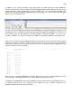
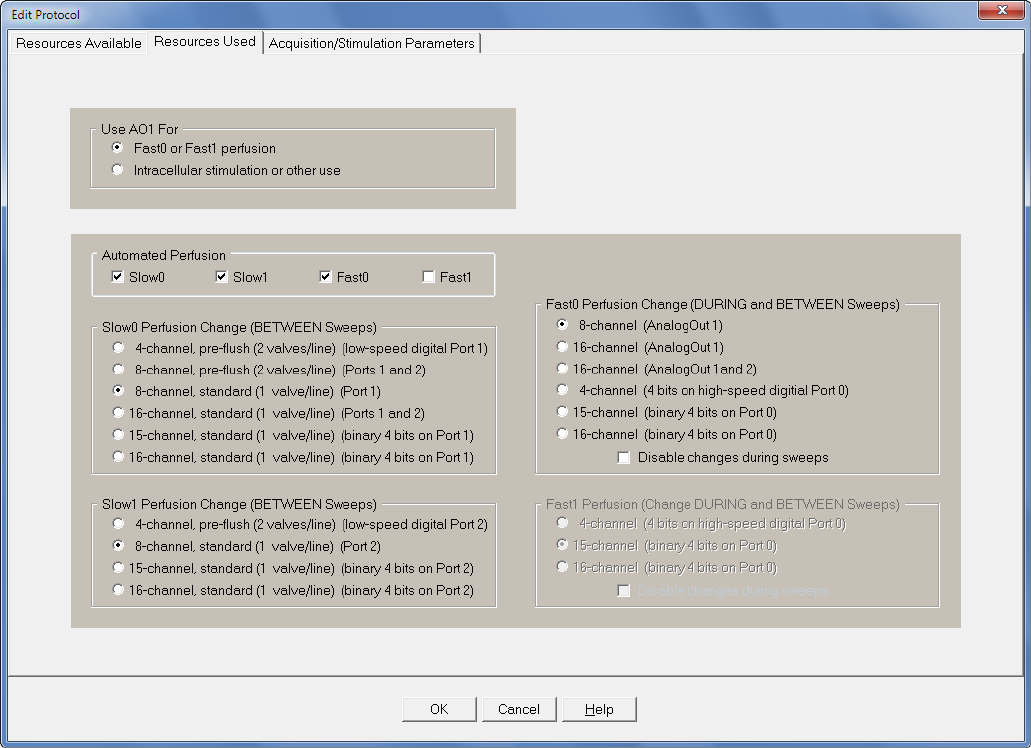
Fig. 10.4.1.2. The ResourcesUsed tabsheet configured to run Dual-Line/Stepper perfusion. First choose
how AO1 will be used. Next check the Slow0, Slow1 and Fast0 perfusion checkboxes. Finally choose
the digital and analog output to control the Slow0 and Slow1 valve controllers and the Fast0 controlled
stepper.
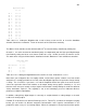
Next you have to set up the perfusion channel label information (Fig. 10.4.1.3, B-D). In the Slow0 (B),
Slow1 (C) and Fast0 (D) channel labels, put in the appropriate perfusion channel labels. In this example,
for Slow0 (the Tube 0 valve controller), the Slow0 Perfuse event in the Protocol Builder can either output
agonist 1 or agonist 2 (‘Tube0 Ag1’ or ‘Tube0 Ag2’). For Slow1 (the Tube 1 valve controller), the ‘Slow1
Perfuse’ event in the Protocol Builder can either output ACSF, antagonist 1 or antagonist 2 (‘Tube1
ACSF’, ‘Tube1 Antag1’ or ‘Tube1 Antag2’). For Fast0, the stepper can switch between ‘Tube0’ or
‘Tube1’.
Then in the Channels tabsheet (Fig. 10.4.1.3A), set which Slow0 and Slow1 perfusion channel will be on
when the MainProtocol is off. Enter the Ch number by the ‘Apply’ button and then click the ‘Apply’ button.
The perfusion channel number when the MainProtocol is off will be shown above the ‘Apply’ button plus