
User manual


176
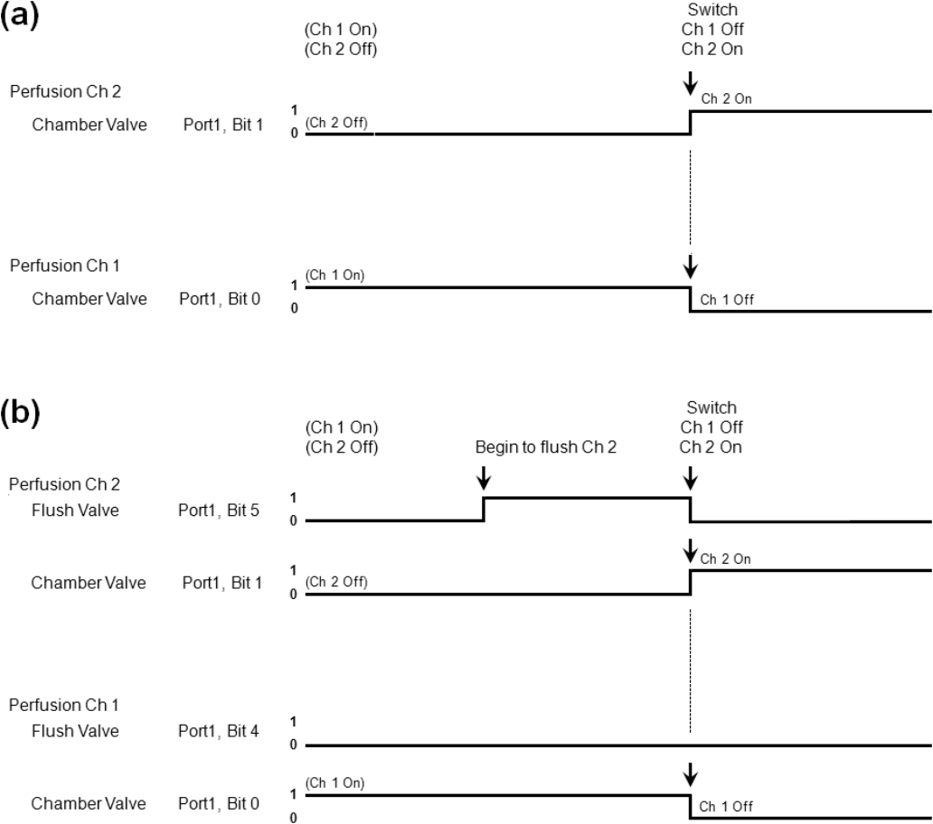
The digital output switching that causes the switching from Ch 1 to Ch 2 for a standard 1 valve/line
perfusion system and for a pre-flush 2 valves/line perfusion system are shown in Fig. 10.2.4.2A and B,
respectively.
The standard system starts out with Ch1 on (and Port1, Bit 0 = logical 1), and Ch 2 off (and Port 1 Bit 1 =
logical 0). When Ch 1 is switched off, and Ch 2 switched on, Port1, Bit 0 switches to logical 0 and Port1,
Bit 1 switches to logical 1.
The 4-channel pre-flush digital outputs for the Chamber Valves are similar to the standard system.
However, before switching Ch 1 off, and Ch 2 on, the C2 Flush Valve turns on (by switching Port 1, Bit 5
to logical 1) for a period of time sufficient to put aerated perfusion fluid in the line between the reservoir
and the T-fitting.
Fig. 10.2.4.2. Switching from Ch 1 to Ch 2 using a Perfusion Controller set up (a) in a standard 8-
channel configuration, and (b) in a pre-flush 4-channel configuration. Note how the Ch2 Flush Valve (Bit
5) turns on before the switch from Ch1 to Ch2 and then turns off at the switchover.