
User manual


107
However, coastline will also increase with extraneous high frequency noise and you should be sure that
sufficient external low-pass analog (Section 2.14) or internal low-pass digital filtering (Section 4.5.4) is
applied to the waveform when the Coastline measurement is made.
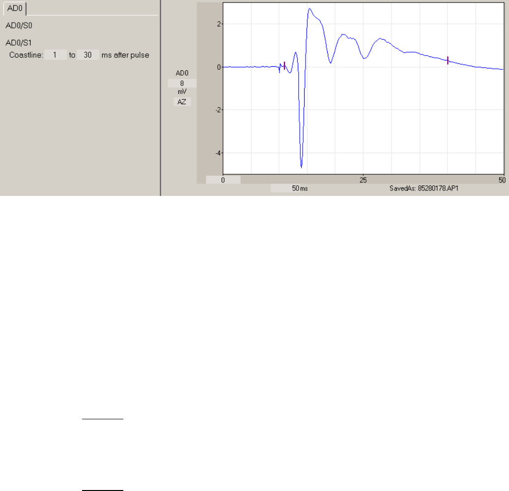
Fig. 4.11.8.1. Detection of Coastline. The Coastline is measured between the left and right bracket
located on the waveform.
4.11.9 PopSpike Amplitude and Latency
The PopSpike Amplitude is calculated as the amplitude from the PopSpike peak to the intersection with
an interpolated tangent dotted line drawn between the pre-PopSpike peak to the post-PopSpike peak
(shown be the solid vertical line in Fig. 4.11.9.1). PopSpike Latency is calculated as the time between the
occurrence of stimulus pulse and the PopSpike peak. PopSpike Amplitude and PopSpike Latency do not
depend upon DC baseline or Peak Amplitude.
In order to use this tangent autodetection method correctly you must first set the PopSpike to be
positive or negative by setting the Pos/Neg field in
PSamp: Pos/Neg ___ to ___ ms after pulse
If Peak Amplitude is also to be calculated then the above line is just
PSamp: Pos/Neg
Next, you must set the time range the PopSpike will be detected over by the "__to__ms after pulse" fields
above. (If Peak Amplitude it to be calculated then use the time fields in the "Peak: Auto/Pos/Neg __ to __
ms after pulse) This time range is shown between the left and right bracket located on the waveform in
Fig. 4.11.9.1.