
User manual


104
4.11.4.4 Low% -> High% of Peak Amplitude
The fourth method, the Low% -> High% Peak Amplitude calculates the slope beginning time point by
using the time where the voltage/amperage was say 20% of the Low% Peak Amplitude value. It
calculates the slope end time point by using the time where the voltage/amperage was say 80% of the
High% Peak Amplitude value. If this method is chosen, the Pulse Detection Panel appears with the
following fields:
Slope: ___ to ___ % peak amplitude
where the first % field is the Low% field and the second % field is the High% field.
All methods have their advantages, but in general the Maximum Slope method is best (with or without
low-pass filtering). If the latency between the stimulus pulse and the slope shifts with time, the Maximum
Slope (with or without low-pass filtering) or the Low% -> High% Peak Amplitude methods are best.
However, when the EPSP/EPSC amplitude approaches 0, the Low% -> High% method begins to
calculate slopes made of noise and therefore gives spurious result. In contrast, the Begin -> End
Times method continues to accurately measure the slope when the EPSP/EPSC amplitude
approaches 0. This problem does not occur as much with the Maximum Slope method.
With the proper amount of low-pass digital filtering, a short Maximum Slope will yield the most accurate
measurement of the maximum slope, and will best deal with shifts in EPSP/EPSC latency and very low
EPSP/EPSC amplitudes.
Slope detections in our group are usually of 0.6 to 2.0 msec duration. When sampling every 100 µsec, this
is 7 to 21 AD samples, respectively. Without low-pass digital filtering, the longer the slope duration the
better, provided the slope still remains on the (somewhat) ‘straight’ part of the EPSP/EPSC. On-line signal
averaging will also decrease slope error measurement.
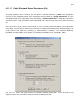
4.11.5 Area
Area calculates the area of the peak more negative or positive than the pre-pulse DC Baseline and is
measured in mV*ms or pA*ms. The Area is measured between the
Peak: Auto/Pos/Neg ___ to ___ ms after pulse
time fields shown by the solid horizontal Area line of the Pulse Detection Panel in Fig. 4.11.5.1. Just as
with the Peak Amplitude measurement, the Auto/Pos/Neg field determines whether the peak will be
Automatically (Auto) determined to be positive or negative, forced to be Positive (Pos), or forced to be
Negative (Neg).
Notice, that when the waveform goes to the opposite polarity of the peak, those values are not calculated
in the area (for example, in Fig. 4.11.5.1, when the waveform goes positive after 16 ms, the area is only
between the first ‘Peak’ time field and up to 16 ms after the pulse.