
User manual


103
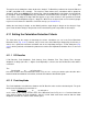
Fig. 4.11.4.1.1. The Maximum Slope Method using no low-pass digital filtering.
4.11.4.2 Maximum Slope (using Low Pass Digital Filtering)
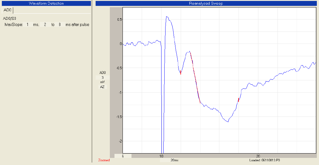
Although the Slope fits a straight line to the “straight” part of the rising phase of the EPSP/EPSC, the
rising phase is usually not a straight line, and is more accurately measured by getting the maximum slope
of a shorter straight line. But there is a tradeoff between getting the correct maximum slope using a short
straight line, and measuring a slope of noise. To help get a more correct maximum slope measurement
using a short straight line, the trace should be low-pass digitally filtered (Section 4.5.4) to an empirically
determined level such that the peak amplitude is not attenuated.
This is probably best used during Reanalyis when different levels of low-pass digital filtering and different
levels of MaxSlope time can be empirically tried. And then compare these results to Maximum Slope
(with no Low Pass Digital Filtering) and slope measured with Beg -> End Times. To my surprise, when
analyzing synaptic potentials the results using longer Maximum Slope (using Low Pass Digital Filtering)
were about identical with the shorter Maximum Slope (using Low Pass Digital Filtering).
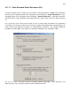
4.11.4.3 Begin -> End Times
The third method, the Begin -> End Times, merely sets the slope beginning time point and the slope end
time points. This method is a much more reliable way of measuring slope when the amplitude of the
synaptic potential can be zero (synaptic failures) and there are no latency shifts in the synaptic potential.
If this method is chosen, the Pulse Detection Panel appears as in Fig. 4.11.2.1. The slope beginning and
end time points are the time fields:
Slope: ___ to ___ ms after pulse