
User manual


102
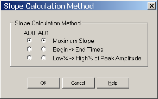
Fig. 4.11.4.1. Slope Calculation Method Dialog Box.
Often there is no one best method of measuring slope, and using two methods is better. For example,
when there are large latency shifts in the synaptic potential, and the amplitude of the synaptic potential
sometimes goes to zero (ie with synaptic failures), a combination of Maximum Slope measurement (with
no low pass filtering) to measure the large amplitude synaptic potential slopes, and Begin -> End Times
slope measurement to measure the zero and very low amplitude potential slopes will give the best slope
measurement.
4.11.4.1 Maximum Slope (with no Low Pass Digital Filtering)
The first method, the Maximum Slope method (with no low-pass filtering), was added as a more reliable
way of measuring slope for conditions where the latency shifts in the synaptic potential and the slope of
the synaptic potential is small (close to noise level). The problem of this method is when there is no
synaptic potential (ie synaptic failure), the slope still measures the maximum slope of the noise and is
therefore never zero.
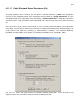
To use the MaximumSlope measurement (Fig. 4.11.4.1.1), set the MaxSlope time field ("1 ms" in this
figure, marked by a red slope line) so that it is within the larger BegTime/EndTime range ("2 to 8 ms after
pulse" in this example, marked by solid vertical lines on the trace).
MaxSlope: ___ ms, ___ to ___ ms after pulse
In this example, the MaxSlope algorhythm will start at 2 ms after the pulse and calculate the value of a 1
ms slope every 0.1 ms until the EndTime point is reached at a slope between 7 and 8 ms after the
pulse. The absolute largest positive or negative slope will be the one chosen and plotted using the
red slope line).
This is the easiest method to use on-line and is therefore the default method.