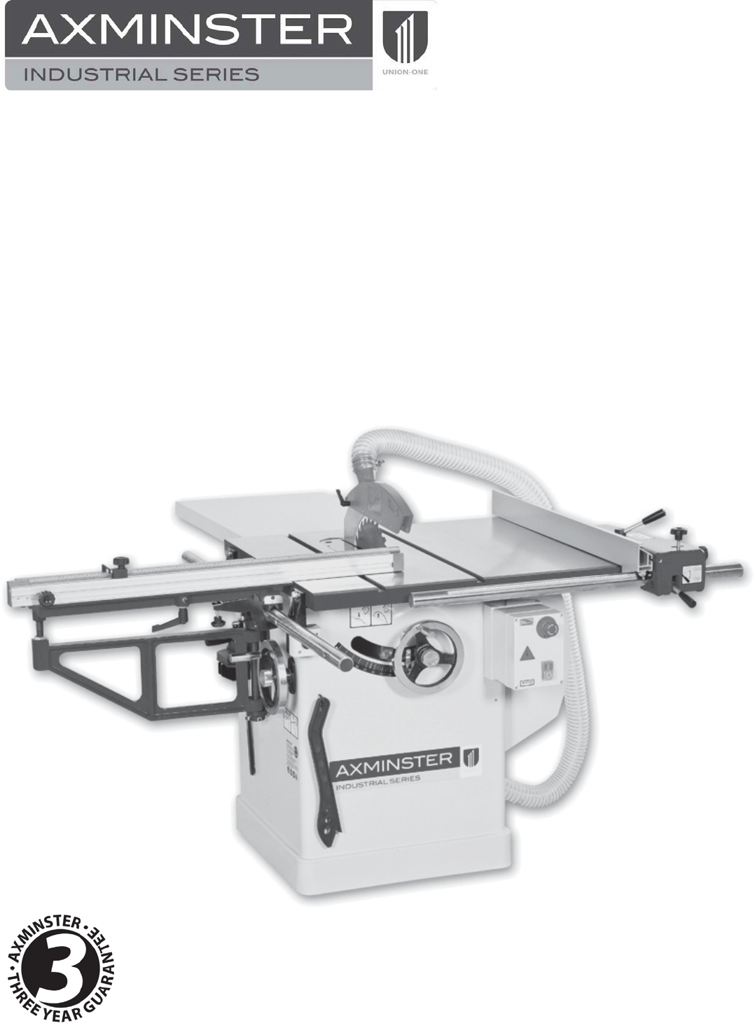
Code 700158 Code 600807 TSCE-12R 305mm Table Saw
List of Contents 1. 2. 3. 4. 5. 6. 7. 8. 9. 10. 11. 12. General Information . . . . . . . . . . . . . . . . . . . . . . . . . . . . . . . . . . . . . . . . . . . . 2 Safety Rules. . . . . . . . . . . . . . . . . . . . . . . . . . . . . . . . . . . . . . . . . . . . . . . . . . . 3-9 Contents of Warning Labels. . . . . . . . . . . . . . . . . . . . . . . . . . . . . . . . . . . . . . 10 Shipping Contents. . . . . . . . . . . . . . . . . . . . . . . . . . . . . . . . . . . . . . . . . . . . . .
ADDITIONAL MARKINGS 1. The following warning also appears on the tool and in the Instruction Manual per UL987. WARNING: FOR YOUR OWN SAFETY READ INSTRUCTION MANUAL BEFORE OPERATING TOOL: (a) Wear eye protection. (b) Use saw-blade guard and spreader for every operation for which it can be used, including all through sawing. (c) Keep hands out of the line of saw blade. (d) Use a push-stick when required. (e) Pay particular attention to instructions on reducing risk of kickback.
7. DON'T FORCE TOOL. It will do the job better and safer at the rate for which it was designed. 8. USE RIGHT TOOL. Don't force tool or attachment to do a job for which it was not designed. 9. The installer shall follow local regulations and National Electrical Code, ANSI/NFPA 70 installation requirements 10. WEAR PROPER APPAREL Do not wear loose clothing, gloves, neckties, rings, bracelets, or other jewelry which may get caught in moving parts. Non-slip footwear is recommended.
2. Safety Rules Warnings 1. Read and understand the entire owner's manual before attempting assembly or operation. 2. Read and understand the warnings posted on the machine and in this manual. Failure to comply with all of these warnings may cause serious injury. 3. Replace the warning labels if they become obscured or removed. 4. Do not use this table saw for other than its intended use.
Warnings 16. Provide for adequate space surrounding work area and non-glare, overhead lighting. 17. Keep the floor around the machine clean and free of scrap material, oil and grease. 18. Keep visitors a safe distance from the work area. Keep children away. 19. Make your workshop child proof with padlocks, master switches or by removing safety keys. 20. Give your work undivided attention. Looking around, carrying on a conversation and “horse-play”are careless acts that can result in serious injury. 21.
Warnings 35. Ground all machines. It should make sure the “PE”terminal being connection before machine operating. 36. Don't use in dangerous environment. Don't use machine in damp or wet locations, or expose them to rain. Please provide a suitable illumination around the machine for safety operation. 37. Please wear eye-shied and ear-shield during operation. 38 Don't force machine. It will do the job better and be safer at the rate for which it was designed. 39.
enable the user of the machine to make a better evaluation of the hazard and risk. 47. After switching off the saw motor, allow the sawblade to stop freely. Never attempt to stop the cutting by hand or other objects. 48. Never cut the wood plate if there is no completed width or too small. 49. The max. rotation speed marked on the saw blade must not be exceeded. 50. The machine shall be not loaded with more than workpiece at a time. 51. During making wooden cases, it will emit harmful dust.
b) Selection of sawblade and riving knife: The operator should only select sawblade of a dismeter and thickness suitable for the machine, as specified in the appendix A. c) Selectin of riving knife slot- The riving knife guiding slot should be no more than 0.5mm wider than the riving knife guiding elements. d) Fixing of sawblade to spindle: Where the spindle diameter is less than the sawblade bore diameter, flanged bushes provided by the machine manufacture should be used to make up the difference.
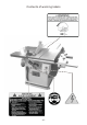
Contents of warning labels - 10 -
Shipping Contents Unpacking Remove box and wood crating completely from around saw. Check for shipping damage immediately to your distributor and shipping agent. Do not discard any shipping material until the Table Saw is assembled and running properly. Compare the contents of your container with the parts lists in the next two pages to make sure all parts are intact. Missing parts, if any, should be reported to your distributor.
Specification Model Code Rating Power Blade Dia/Bore Blade Tilt Max Depth of Cut @ 45˚ Max Depth of Cut @ 90˚ Max Width of Cut with Fence Table Size Table Height Sliding Table Size Dust Extraction Outlet Min Extraction Airflow Required Overall L x W x H Weight TSCE-12R 600087 Industrial 3.
Foundation Drawing TSCE-305R 2235mm 625mm 1400mm 640mm 898mm 800mm 650mm - 13 -
- 14 -
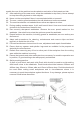
Assembly Motor Cover Assembly ˙Tool: 6mm Allen Hex Wrench 1.Remove motor cover A (Figure 1) insert on cabinet. 2.Closing the motor cover and fasten cover two screw A (Figure 2). Handwheel Assembly Referring to Figure 3: Hardware: (2) Handle & Handwheel (C), (2) Lock Knob (D), (2) Shaft Key(not snown) A Tools: 3mm hex wrench The front handwheel (E) is installed at the factory. Install the side handwheel (C) as follows: 1.
Extension Wing Referring to Figures 4 and 5: 1. 2. 3. 4. Hardware: (6)7/16”*1-1/2” Hex Cap Bolts, (6)7/16” Lock Washers, (6) 7/16” Flat Washers & (2) Extension Tables Tools: 17mm Wrench, Straight Edge Attach the left extension wing (A) (Figure.4) to the table (B) with three each hex cap screws (E) (Figure.5) lock washers (F) and flat washers (G). so the extension wing can still be manually adjusted but do not tighten.
Riving Knife Installation Description Referring to Figure 7: The complete riving knife and guard assembly is shown in Figure.7 Installation Referring to Figure 8: 1. Set the saw blade to the 90 degree position and raise it all the way (refer to Handwheel Adjustments on Figure 16.) 2. Remove the table insert (J). 3. Located inside the table and accessible through the insert opening (Figure 8 inset), place the quick-release clamp lock handle (K) in the unlock position. 4.
Mounting Rip Fence Support Bracket Adjust the rip fence support Bracket flush with the Table by turning four set screw A (Figure.9) and using a straight edge. Check the water level once again after tightening B (Figure. 9) two hex cap screw. A B Figure. 9 Emergency Foot Operated Stop Switch This switch ( Figure 10.) is provided for use in emergency situation only, do not remove that it is used in lieu of the mushroom headed lock-off stop switch on the front of the switch box.
Mounting Front Guide Bar 1.Mounting the Front Guide Bar A (Figure12) to the front of the saw Table B (Figure12). 2.See the Rip Fence Alignment instructions. This will address the mounting of rail and Rip fence. A B Figure 12 Rip Fence Alignment Burning on the waste side of stock and/or the workpiece binding between the rip fence and the back of the saw, are both indicative of the rip fence being out of square to the blade.
Sliding Table Setting & Installation-Option If the cross cut table is not set parallel to the saw blade this causes heeling; that is ; the blade is not parallel to the saw cut. Heeling is hard on the blade and can cause excess vibration .Start by checking that the cross cut shaft is level to the top of the table . The Two Hex Bolt that are used to fasten the bar to the table and the bar can therefore be adjusted to suit. To do this, simply follow these direction: With the rolling table removed.
Roll the table through its full travel, checking that the gap remains the same all the way along the table. If the gap varies from one end to the other loosen the jib support bracket and adjust it either leftwards or rightwards. It is important that the bracket is re-tightened once adjustments have been made (4mm Hex Wrench required) After the table has been lined up square the crosscut fence to the blade and re-set the 90° stop if necessary .
Riving Knife Adjustment B Lateral alignment The saw blade and riving knife must be in line as close as possible with each other (lateral alignment) for the prevention of kickback. Upon initial blade guard and riving knife installation no further adjustment should be necessary. Alignment should be checked and adjusted, if required, after each blade change. Check the alignment as follows: 1. Remove the blade guard (Figure 15). 2. Place a straightedge (A, Fig.
4. Tighten the socket head flat screws (E). 5. Reinsert the riving knife; tighten the lock handle (A, Fig. 17) and check that the saw blade/knife gap is between 3-8mm (Figure 18). Note: Attempt to make the gaps as even as possible. Blade Alignment Tools:8mm hex wrench, combination square, marker Blade alignment with the table is adjusted at the factory. After a period of use, or, after moving the saw to another location, the blade may no longer be aligned with the table.
Adjusting 45° and 90° Positive Stops The stops have been adjusted at the factory. After a period of use, or, after moving the saw to another location, the stops may no longer be set properly. To check and adjust the stops: Tools : 12mm wrench, combination square 1. Disconnect saw from power source. 2. Raise the saw blade to its maximum height by using the handwheel. 3. Set the blade at 90 degrees to the table by turning the blade tilting handwheel clockwise as far as it will go. 4.
Changing the Belt WARNING Make all machine adjustments or maintenance with the machine unplugged from the power source. Failure to comply may cause serious injury! Referring to Figure 24: .Tools: 17mm Wrench 1. Disconnect the machine from the power source, unplug. 2. Lower the blade to its lowest point. 3. Loosen two hex cap bolts (A). 4. Take the tension off of the poly V-Belt (B) by lifting up on the motor. 5. Remove the belt from the arbor and motor pulleys. 6. Replace and tension the belt.
Troubleshooting Trouble Possible Cause Overload tripped Saw stops or will not start Saw unplugged from wall or motor Fuse blown or circuit breaker tripped Cord damaged Stop not adjusted correctly Solution Allow motor to cool and reset by pushing off switch Check all plug connections Replace fuse or reset circuit breaker Replace cord Miter gauge out of adjustment Check blade with square and adjust stops Check blade with square and adjust pointer Adjust miter gauge Material binds blade when ripping Fe
- 27 -
Table and Cabinet Assembly(Right tilt) lndex No. Part No. Description Size Qty. 1………… UOTS10-1…………….…… 2………… UOTS10-2.………………… 3………… UOTS10-3.………………… 4………… UOTS10-4.………………… 5………… UOTS10-5.………………… 6………… UOTS10-6.…………………. Lock Knob………………. ……………... .…1 Miter Gauge Body.……… ……………... .…1 Hex Nut………………….. M5…………. .…3 Pointer…………………… ……………... .…1 Stop Link………………... ……………... .…1 Set Screw.………………... M5ǘǘ5………. .…1 7………… UOTS10-7.…………………. Special Pin………………. M3ǘǘ6………. .…1 8………… UOTS10-8.…………………. Screw……………………..
Table and Cabinet Assembly(Right tilt) lndex No. Part No. Description Size Qty. 28……….. UOTS10-28…..……………. 29……….. UOTS10-29…..……………. 30……….. TSCE10-30……………….... …………. TSCE12-30…………..…..… 31……….. UOTS10-31……………….… Tilt Scale…………………… Logo Lable………………… Power Cord………………... Power Cord………………... Carriage Bolt……………… ……………... .…1 ……………... .…1 ……….……. .…1 ……….……. .…1 1/4”ǘǘ3/4”..… .…4 32……….. TSCE10-32…………..…….. 33……….. UOTS10-33………..……….. …………. UOTS10-33A…..…………… …………. UOTS10-33B…..…………… …………. UOTS10-33C…..
Table and Cabinet Assembly(Right tilt) lndex No. Part No. Description Size Qty. 54……….. 901M06016…………………. Hex Socket Head Screw.…. M6ǘǘ16……... .…2 ǘ1/2…… .…2 55……….. 906316012…………………… Screw…………………….. 3/16ǘ 56……….. S12200015…………………... Foot Stop Switch…………... ……………... .…1 57……….. 914M051001………………… Flat Washer………………... M5…………. .
Motor and Trunnion Assembly - 31 -
Motor and Trunnion Assembly - 32 -
Motor and Trunnion Assembly - 33 -
Motor and Trunnion Assembly - 34 -
Motor and Trunnion Assembly - 35 -
Blade Guard Assembly - 36 -
Blade Guard Assembly - 37 -
- 38 -
Rip Fence Assembly lndex No. Part No. Description Size Qty. 1………... 231-1111……………………… Rip Fence Bracket……… …………….. .…1 2………... 231-1112……………………… Clamping Block………... …………….. .…1 3………... 231-1113……………………... Nylon Nut……………….. M10………. .…1 4………... 231-1114……………………... Flat Washer…………….. M10………. .…1 5………... 231-1115……………………… Knob……………………. ……………. .…1 6………... 231-1116……………………... Fiber Washer…………… M10……….. .…1 7………... 231-1117……………………… Knob…………………….. …………….. .…1 8………... 231-1118……………………… Handle………………….. ……………..
Rip Fence Assembly lndex No. Part No. 34……….. 231-11134……………………. 35……….. 231-11135……………………. 36……….. 900-21……………………….. 37……….. 231-11137……………………. 38……….. 231-11138……………………. 39……….. 231-11139……………………. 40……….. 900-22……………………….. 41……….. 31C64………………………... Description Size Stop Profile……………… …………… Sticker…………………… ……………. Cursor Base…………….. ……………. Flat Washer……………... M4……….... Lock Washer……………. M4……….... Round Head Screw……... M4x10...…… Cursor Housing………… …………….. Cursor…………………… …………….. - 40 - Qty. ….1 ….
- 41 -
Sliding Table System Assembly (UST-36) Index No. Part No. 1………… UST-36-01………………… 2………… UST-36-02………………… 3………… UST-36-03………………… 4………… UST-36-04………………… 5………… UST-36-05………………… 6………… UST-36-06………………… Description Size Qty. Hex Socket Cap Screw… Guide Tube……………… Guide Rail Bracket…....... Plate……………………… Hex Nut………….……... Hex Socket Cap Screw..... 3/8”x1”….... .…2 ……………... .…1 …..…………. .…2 ……………... .…1 M8………... .…1 M8ǘ20…….. .…1 7………… UST-36-07………………… Special Bolt……………… ……….……. .
Sliding Table System Assembly (UST-36) Index No. Part No. 34……….. UST-36-34………………… 35……….. UST-36-35………………… 36……….. UST-36-36………………… 37……….. UST-36-37………………… 38……….. UST-36-38………………… 39……….. UST-36-39………………… 40……….. UST-36-40………………… 41……….. UST-36-41………………… 42……….. UST-36-42………………… 43……….. UST-36-43………………… 44……….. UST-36-44………………… 45……….. UST-36-45………………… 46……….. UST-36-46………………… 47……….. UST-36-47………………… 48……….. UST-36-48………………… 49……….. UST-36-49………………… 50……….. UST-36-50………………… 51………..
- 44 -
- 45 -
The Axminster guarantee is available on Hobby, Trade, Industrial, Engineer, Air Tools & Axcnc Technology Series machines It’s probably the most comprehensive FREE guarantee ever- buy with confidence from Axminster! So sure are we of the quality, we cover all parts and labour free of charge for three years! s ,OOK FOR THE ICON AND PUT YOUR TRUST IN !XMINSTER s .