
User manual

08
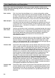
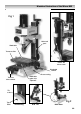
Parts Identification and Description
Please take some time to identify the various parts of your machine so that you are
familiar with the terminology we will use to enable you to set up and operate your Mill
safely and correctly.
Base casting This is the ‘Stand’ for the milling m/c. It is a square casting with a seating
flange to the rear, which mounts the Tilt Housing for the Main Tool Post. There
are 4 No. 8.75mm holes in the approximate corners of the base to enable it to
be bolted to a bench or the stand. There is also a dovetail slide machined on
the front top surface of the base, to mount the traverse slide of the worktable.
Main tool post This is the column of the mill, it is an 65 x 50 bar with a dovetail slide
machined on the front onto which the milling head is mounted, the lower part
is the circular ‘boss’ for the tilt assembly. On the left side of the post a scale,
graduated in mm’s, is mounted to read against an adjustable pointer mounted
on the head casting.
Rise and fall The Rise and Fall drive screw is anchored in a machined housing at the top of
drive screw the main tool post. It has a wheel and rod handle keyed to the shaft to enable
the screw to be turned. It is fed through a threaded dog that is bolted to the
head casting allowing the head to be moved up and down. Viewed from
above the drive screw is turned clockwise to raise the head and
anti-clockwise to lower it.
Tilt housing The tilt housing is mounted to the base casting using 4 bolts. The tilt ‘boss’ of
the main tool post is mated to the housing and clamped by a further 4 bolts.
The main tool post can tilt 45(degrees) from the vertical either left or right.
There is an adjustable pointer and a scale mounted on the housing to give an
indication of the amount of tilt that has been applied.
Traverse slide The traverse slide casting mounts onto the dovetail slide of the base casting.
There is a gybe strip fitted to the right side dovetail to maintain the fit. In the
front face of the slide is a machined housing which mounts and anchors the
drive shaft for the traverse feed. Under the slide (on the base) is a threaded
dog mounted in a fixed position, through which the traverse drive shaft is
threaded so as to enable the slide to be driven back and forth. The top of the
traverse slide has a female dovetail machined into it, perpendicular to the
lower dovetail. This marries with the dovetail on the underside of the
worktable. The front face of the dovetail is fitted with a gybe strip to maintain
the fit. The top of the slide also has a fixed threaded dog mounted to it,
through which the drive shaft of the worktable is threaded to allow the
worktable to be driven from side to side. In between the grubscrews and
locknuts of the gybe strip adjustors is an M4 caphead bolt that can be driven
forward to clamp the gybe strips against the dovetails to enable the traverse
and longitudinal movements to be locked in position.
Traverse slide The traverse slide is driven using the wheel and rod handle at the front of the
control machine. Behind the boss of the handle is a graduated ring (thimble) so that
the movement of the slide can be measured. The thimble is held to the drive
shaft by friction, and can be pre-positioned to a predetermined start or stop
dimension.