
User manual

10
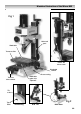
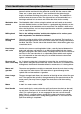
Parts Identification and Description (Continued)
Worktable The Worktable is a machined casting 240mm long by 145mm wide. There is a
dovetail section machined in the underside to mate with the traverse slide.
There are 3 x 8mm open ended ‘T’ slots machined in the table along its
length, to facilitate the fixing of machine vices or clamps. The worktable is
mounted onto the traverse slide. The right end face of the worktable has a
housing machined in it to mount and anchor the drive shaft assembly.
Worktable drive The Worktable slide is driven using the wheel and rod handle at the end of
control the table. Behind the boss of the handle is a graduated ring (thimble) so that
the movement of the worktable can be measured. The thimble is held to the
drive shaft by friction, and can be pre-positioned to establish a predetermined
start or stop dimension.
Milling head This is the ‘milling machine’ and the descriptions of its various parts
and components are detailed as follows:-
Milling head The main casting to which all the components are attached. The head has a
casting dovetail housing machined at the rear, which allows the casting to be fitted to
the Main Tool Post. The left side of the dovetail slide is fitted with a gybe strip
to maintain the fit.
Head clamp Similar to the traverse and longitudinal slides, centrally located between the
and scale gybe strip adjusters and locknuts is an M4 bristol handled bolt that clamps
the gybe strip against the slide to effect a locking action for the rise and fall of
the head. In the same location is an adjustable pointer which reads against
the scale mounted on the main tool post, to enable the head to be moved
against a reference point.
Rise and fall An ‘L’ shaped casting that is threaded to accept the rise and fall drive screw,
drive screw dog and is driven along the thread when the screw is turned. As it is bolted to the
milling head, the head will therefore follow its movement as it is being driven.
Motor and The motor and gearbox assembly are mounted above the main head casting
gearbox at the top of the arbor sleeve. The motor drive is geared through to the
spindle with an intermediate 2:1 gearbox.
Gear change The gear change knob allows the selection of the high or low ratio of the gear
knob train. The speed of the spindle is then governed by the speed control on the
motor panel. (You may have to ‘joggle’ the chuck/tool to aid the meshing
action).
Motor A 220V d.c. motor rated at 150W.
Feed Handle Lever handle that is used to drive the quill (and hence the chuck or the tool)
up and down. The boss of the handle is fitted to the end of a ‘splined’ gear
shaft. This ‘splined’ gear is, in turn, engaged in the rack cut into the quill
body. There is a counter balance spring in the arbor and sleeve assembly,
giving a more controlled ‘feel’ during drilling operations. It also retracts the
quill when drilling is completed.