SIEG C1 Micro Lathe Mk2 w w w. a x m i n s t e r. c o .
Index of Contents Page No. Index of Contents.............................................................................................................................................. 2 Declaration of Conformity………….………........……..…………...................................................................2 What’s in the Box………….………........……..………….....................................................................................3 General Instructions for 230v Machines.......................................
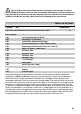
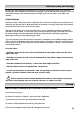
! Please read the Instruction Manual prior to using your new machine; as well as the installation procedure, there are daily and periodic maintenance recommendations to help you keep your machine on top line and prolong its life. Keep this Instruction Manual readily accessible for any others who may also be required to use the machine. What’s in the Box? Quantity Item 1 No. Micro Lathe with Chuck, Chuck Guard and Tool Post fitted. Box containing:1 No. 1 No. 3 No. 1 No. 1 No. 1 No. 1 No. 1 No. 1 No. 1 No.
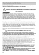
General Instructions for 240v Machines Good Working Practices/Safety The following suggestions will enable you to observe good working practices, keep yourself and fellow workers safe and maintain your tools and equipment in good working order. ! WARNING!! KEEP TOOLS AND EQUIPMENT OUT OF THE REACH OF YOUNG CHILDREN Mains Powered Tools Primary Precautions Primary Precautions These machines are supplied with a moulded 13 Amp. Plug and 3 core power cable.
Initial Assembly and Testing Ideally, your lathe should be installed close to a correctly rated power supply, in a warm dry environment, well ventilated and illuminated by bright clear natural light, with adequate access all around the machine, and sufficient adjacent storage space for your tools, accessories and material.
Testing (Continued) f) Check the Autofeed/Manual Lever is set to manual (Hand logo). g) Close the chuck guard. h) Check the speed control is switched OFF (fully anti-clockwise). i) Check the Forward/Off/Reverse Switch is in the Off position. j) Connect the machine to the mains supply and switch power on. k) Turn Emergency Stop switch to the right and allow it to spring out and reset. l) Check the Green Power LED is illuminated. m) Turn the Speed Control Switch On (Clicks On).
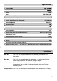
Specifications Axminster No. SIEG C1 MK2 600882 Rating: Hobby Motor: 240V 50Hz 150W Max Swing over the Bed: 140mm Max Distance Between Centres: Spindle Speed (Forward & Backward): Reversing Method: 250mm 100-2000rpm Electrical Headstock Taper: 2MT Tailstock Taper: 1MT Clear Bore in Headstock Mandrel: 10.5mm Leadscrew Pitch: 3mm Thread Pitch Range (Change Wheel Set Req): 0.5,0.7,0.8,1.0,1.
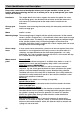
Parts Identification and Description Please take some time to identify the various parts of your machine so that you are familiar with the terminology we will use to enable you to set up and operate your Lathe safely and correctly. Headstock The ‘engine block’ of the lathe, supports the motor, the spindle, the cover for the change gears, the drive belt and the driven end of the leadscrew. It also mounts the control panel for the motor and the selector for the leadscrew.
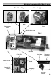
Machine Illustration of the Micro-Lathe (Chuck & safety cover removed for clarity) Mounting flange Chuck adaptor plate Change gear cover Chuck Headstock Chuck safety cover Fig 1 Gear change cover knob Lathe bed Fault LED Hand logo Triangular Waveform logo Speed control knob Power on LED Fuse cap Forward/Off/ Reverse switch Emergency stop (Motor control panel) Leadscrew selector 09
Parts Identification and Description (Continued) Leadscrew selector A round centre rib switch/lever, which allows selection of the leadscrew to ‘autofeed’, i.e driven by the change gear train, (indicated by a triangular waveform sign), or ‘manually’, i.e. driven by the handle on the end of the leadscrew, (indicated by a ‘hand’ logo). Lathe bed Solid cast, machined bed.
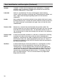
Machine Illustration of the Micro-Lathe (Continued) Fig 2 Traverse slide Tranverse slide gybe strip adjustors Tool post Traverse slide control Lathe bed Tool post securing bolt Saddle Typ.
Parts Identification and Description (Continued) Gear change cover knob A reeded knob screwed into the front of the headstock, it locates in a slot in the change gear cover, and is used to secure the cover shut. It is unscrewed to release the cover to allow it to be swung open. Tailstock A machined casting that accurately fits to the lathe bed. It carries the tailstock barrel. The tailstock barrel is machined with a No.
Machine Illustration of the Micro-Lathe (Continued) Motor securing bolts Fig 4 Gear change table Tailstock centre Tailstock Tailstock barrel control Fig 5 Tailstock barrel lock Tailstock clamping bolts Leadscew (Unseen) Leadscrew drive handle 13
Machine Illustration of the Micro-Lathe (Continued) Fig 6 (Splash guard removed for clarity) Saddle gybe strip adjustors Motor Motor brush caps Motor brush caps 14
Settings and adjustments ! Your microlathe has been factory set and adjusted, however, during its life time you may find occasion whereby the lathe needs adjusting to maintain its accuracy and optimum performance. These adjustments can be made as follows:- Saddle and Traverse slide adjustment The saddle and the traverse slide are both mounted over dovetail sections.
Maintenance Your Microlathe is a precision tool. In order to maintain this precision and prolong its useful life, it is advised that you follow the recommended daily and periodic maintenance tables printed below. Daily Carry out a visual inspection. Repair any damage immediately. Minor damage to the beds should be taken out with an oilstone. Move the saddle and the traverse slide back and forth by hand, check that the movement is smooth. Spread a light film of oil over the bed and the traverse slide bed.
Maintenance (Continued) Monthly Check the belt tension. If necessary reset the belt tension by loosening the two motor securing caphead bolts, retension the belt and re-secure the bolts. Every 6 Months Because the d.c. motor has a heavy permanent magnetic field, it is advisable to dismount the lathe every 6 months, remove the splash guard and remove all the swarf that may have found its way into the motor housing.
Illustrated Parts Breakdown for the Micro Lathe (Part 1) 18
Illustrated Parts Breakdown for the Micro Lathe (Part 2) 19
Illustrated Parts catalogue for the Micro Lathe (Part 1) 20
Illustrated Parts catalogue for the Micro Lathe (Part 2) PC Board Replacement Part No: Part No: 600883 21
Micro Lathe (Accessories) 80mm Independent 4 jaw chuck Part No: (100021) Fixed steady Part No: (100026) 50mm Quick vice Part No: (100022) Change gear set Part No: (100030) #1MT Rolling centre Part No: (100032) Vertical slide Part No: 100028) Tailstock chuck + shank Part No: (100031) Travelling steady Part No: (100027) Compound slide Part No: (100029) 112mm T- slot 8mm Face plate Part No: (100025) Tailstock centre Part No: HARD2 8mm (11 piece cutter set) Part No: (SET38TC) 22
Change Gear Table Fig 8 Fig 9 23
SIEG C1 Micro Lathe Mk2 600882 Axminster Reference No: C1 Mk 2 Part No: 600882 W AXMINSTER W H I T E Axminster Devon EX13 5PH UK FREEPHONE 0800 371822 2004 www.axminster.co.