Code 501199 SBW3501B Bandsaw AT&M: 04/09/2014 REF: 508308
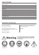
Index of Contents Index of Contents Declaration of Conformity What’s Included General Instructions for 230V Machines Specification Main Assembly Machine Footprint Illustration and Parts Description Setting Up the Saw Operating Instructions Changing the Saw Blade Routing Maintenance Parts Breakdown/List Wiring Diagram 02 02 03-04-05 06 07 07-08-09-10-11-12-13-14 14 15-16-17-18-19-20 21-22-23-24-25 25-26 26-27 28 29-30-31-32-33-34 35 Declaration of Conformity Copied from CE Certificate manufactured by OAV
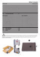
What’s Included Quantity Item Model Number SBW-350 1 No (Code: 501199) 1 No SBW3501B Bandsaw Bandsaw Blade 2552,mm (100.1/2”) long, mounted on saw but not tensioned.
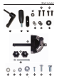
What’s Included 2 2 3 4 5 6 7 4
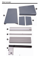
What’s Included 11 12 14 13 16 15 8 9 10 17 18 19 20 21 22 23 24 5 25 26
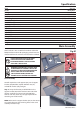
General Instructions for 230V Machines Clean the machine with a damp soapy cloth if needs be, do not use any solvents or cleaners as these may cause damage to any plastic parts or to the electrical components. Good Working Practices/Safety The following suggestions will enable you to observe good working practices, keep yourself and fellow workers safe and maintain your tools and equipment in good working order.
Specification Code 501199 Model SBW3501B Rating Trade Power 550W 230V Blade Speed 800m/min Blade Length 2,552mm(100.
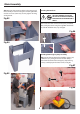
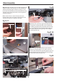
Main Assembly Step 2 Line up the remaining holes in the two parts of the assembly and secure using the remaining M6 bolts, washers and nuts (20-22-25), securely tighten all fixing, see figs 03-04. Mounting the Bandsaw WARNING!! When mounting the unit, we strongly advise you get the assistance of another person because the bandsaw is heavy . Fig 03 Lift the saw on to the stand and line up the pre-drilled holes, see fig 05, secure using the eight M8 coach bolts (26) and M8 shoulder nuts (23), see fig 06.
Main Assembly Fig 13-14 Step 2 Line up the two elongated holes in the rear of the emergency stop housing with the two pre-drilled holes to the front of stand, insert one of the domed Phillips screw through the housing and while holding it in place screw on the M4 nut (21) and finger tighten. Repeat for the opposite side then fully tighten the fixings, see figs 09-10-11. A Step 3 Carefully replace the outer housing and tighten the four Phillips screws, see fig 12.
Main Assembly Step 2 Remove the table insert and table alignment pin and place safely aside, see figs 16-17. Lift the table (1), slide the blade through the table slot, see fig 18, line up the two threaded bolts to the underside of the table and lower them through the holes in the tilt quadrant assembly, see fig 19. Fig 20 18 Make sure the table is seated correctly on the tilt quadrant then screw on the two clamping knobs (18) to clamp the table (1) in position, see fig 20.
Main Assembly Step 1 Place a washer (14) over each M6x20mm bolt (12), line up the elongated holes in the front fence rail (4) with the pre-drilled holes to the front of the cast iron table (1), introduce the two M6x20mm bolts (12) through the fence rail and lightly tighten using the supplied spanner (22), see figs 27-28-29-30.
Main Assembly Fig 32-33-34 Fig 36 Adjustable guide rest 5 Step 4 Locate the M8 nut (16), and screw it onto the thread of the M8 threaded lever (9) then screw the threaded lever (9) into the threaded hole in the clamp assembly (7) mechanism and tighten the nut with a spanner, see figs 37-38.
Main Assembly Fig 39 Fig 43 6 10 13 8 Fig 40-41-42 Fig 44-45 13 10 Magnifying scale 7 Step 7 Introduce the ‘T’ slot to the side of the fence (6) over the threaded ‘T’ slot insert (10) and slide on the fence until the fence (6) is flush with the end of the cast iron fence (7). Tighten the lift and shift handle (8), see figs 46-47-48.
Main Assembly/Machine Footprint NOTE: The fence (6) has two positions, vertical and horizontal for cutting narrow pieces, see fig 49-50-51. Fig 49-50-51 1770mm 720mm Mitre Fence Assembly Locate the mitre fence (19) and slide the mitre fence into the table (1) ‘T’ slot, see fig 52.
Illustration and Parts Description Micro door switch Blade tensioning wheel Upper wheel door Upper door locking knob Upper blade guide adjusting wheel Main saw frame Upper blade guide and guard ON/OFF buttons Saw table ‘T’ slot for mitre fence Mitre fence Fence guide rail Table alignment pin Fence Fence clamp handle Lower door locking knob Emergency stop button Lower wheel door Bandsaw stand 15 Continues Over....
Illustration and Parts Description Emergency stop, press to stop the bandsaw On/Off buttons Upper door micro switch assembly 17 7 4 Fence clamp assembly (7), Mitre fence (17), Fence rail with scale (4) Upper blade guide height scale and pointer Table levelling stop bolt 16 Scale magnifying glass Upper blade guide height scale and pointer Table insert
Illustration and Parts Description Upper wheel mounting Upper saw wheel Blade Table insert Saw table Drive pulley Lower saw wheel 17 Continues Over....
Illustration and Parts Description B A B A Blade guide fore and aft adjusting knob (A), Rear thrust bearing adjusting knob (B) Blade (A), Tyre (B) C B A A Upper bearing blade guides (A), Rear thrust bearing (B) and rear thrust bearing butterfly clamping screw (C) C B Blade tensioning mechanism B A A Lower bearing blade guide, butterfly clamp and adjusting knob (A), lower bearings guide guard (B) Rear thrust bearing, butterfly clamp and adjusting knob (C) Drive pulley (A), Pulley belt (B) 18
Illustration and Parts Description Quick release tensioning lever for changing the blade Blade tensioning scale Upper blade guide clamp Blade tracking control knob and locking knob Fence clamp lift and shift handle Rear fence guide rail Tilt quadrant assembly Dust extraction outlet Motor 19 Continues Over....
Illustration and Parts Description Blade tensioning scale C A B Quick release tensioning blade lever (A), Tracking control knob (B) and locking knob (C) Upper blade guide clamp B C A Table tilt clamping knob (A), Table tilt scale (B) and pointer with adjustment screw (C) 20 Dust extraction outlet
Setting Up the Saw Fig 53 DISCONNECT THE SAW FROM THE MAINS SUPPLY! Tensioning and tracking the blade Make sure both top and bottom blade guides are well clear of the blade Open the front covers fully, giving good access to the top compartment of the saw and good visibility into the bottom compartment (see page 17). For tracking the blade first adjust all bearing guides so that they’re well clear of the blade. Check that the blade is sitting approximately in the middle of the wheels, see fig 53.
Setting Up the Saw Make sure the upper blade guide is raised as high as possible. Place a square on the table and move it up against the blade (behind the teeth), see fig 60. Fig 57-58 A Check that the blade is perpendicular to the table. If it is not, try resetting the table.
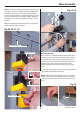
Setting Up the Saw Fig 63 Setting the Blade Guides (above table) DISCONNECT THE SAW FROM THE MAINS SUPPLY! Pointer Lower the upper blade guide to approximately 1 1/2”(38mm) above the table. Clamp in place. Loosen the butterfly screw (A),holding the guide assembly in Adjusting screw place and adjust the fore and aft position by turning the adjustment knob (B) so that the leading edges of the side guide bearings are approximately 2 mm behind the gullets of the saw blade.
Setting Up the Saw Fig 70-71 Fig 73-74 D B 2mm behind the blade Blade Guide bearings set to 0.5 thickness to the blade Thrust bearing Setting the Blade Guides (below table) IT MAY BE EASIER TO SET THE GUIDE BEARINGS IF THE CAST IRON TABLE (1) IS REMOVED, REFER TO MAIN ASSEMBLY INSTRUCTIONS. Loosen the Hex screw (A) holding the guide bearings and move to approximately 0.5mm from each side of the blade. NOTE: A sheet of A4 of photocopy paper is approximately 0.5mm thick.
Setting Up the Saw To adjust the lower thrust bearing, loosen the butterfly screw (D), see fig 80, turn the adjusting knob (E) to move the thrust bearing approximately 2mm behind the blade, see fig 82. Re-tighten the butterfly screw (D). Fig 76-77 C When all adjustments have been made, recheck that when the blade is pressed back against the thrust bearing, both the upper and lower side guides are still behind the teeth of the saw.
Operating Instructions 9. If you are cutting long pieces of material think about sawing cutouts (i.e. a saw cut from the edge of the material to the saw line) along the saw line so that you can discard the off cuts as you progress down the saw line. in hand. Change the blade if necessary. Check the blade is not damaged; is clean, sharp, tracks properly and is correctly tensioned. 3. Set the upper blade guide to approximately 12mm (1/2”) above the height of the work piece. 10.
Changing the Saw Blade Fig 83 Fig 85-86 Tension released Lower guide bearing guards WARNING! BE VERY CAUTIOUS WHEN YOU ‘UNFOLD’ THE BLADE; IT TENDS TO ‘SPRING’ OPEN, BLADE AND TEETH GOING EVERYWHERE. Also check that the blade did not “unfold” inside out. i.e. looking at the right side front of the loop, the teeth should be on the front of the blade and pointing down. If you can’t arrive at this view, turn the blade inside out from its current position and look again.
Routing Maintenance Daily Monthly • Keep the machine clean. • Open the lower and upper door and check the condition of the tyres and the drive belt, see figs 88-8990. • Check the saw blade for missing teeth and cracks, see fig 89. • Spray oil the bare metal surfaces. Weekly • Open the top and bottom wheel covers and clean out all saw dust. • Clean impacted ‘crud’ from the tyres, apply a little oil to the screw threads of the blade and drive belt tensioners. DO NOT USE OIL near the belt.
Parts Breakdown/List Main Saw Assembly 29 Continues Over....
Parts Breakdown/List Key No. Part No.
Parts Breakdown/List 56 130044 FIXED RING 1 57 DD050100 SET SCREW 58 130036 ADJUST SCREW 1 59 130022 SUPPORT SEAT 1 60 130048 SPRING 1 61 130023 INDICATOR 1 62 130019 FREE NUT 1 63 990655 LOCK KNOB 64 990657 KNOB NUT 65 WF061310 FLATWASHER 66 991608 PULL NUT 67 130015 UPPER WHEEL FIXED SEAT 68 130028 FREE KEY 12x12 1 69 SR089400 SOCKET CAP BOLT M8x 16 4 70 WS080000 SPRING WASHER M8 4 71 WF082320 FLATWASHER M8x023 4 72 130026 REVOLVING SPINDLE
Parts Breakdown/List 103 150031 PIN 2 104 Sf059200 PAN HEAD BOLT W/FLANGE 105 130043 RIGHT COVER 1 106 150010 ADJUSTING NUT 4 107 Ss080801 ADJUSTING SCREW 108 150014 THUMBSCREW 109 150206 LOWER SUPPORT BRACKET POST 1 111 135011 POINT 1 112 Sh069300 HEX HEAD BOLT 113 Wf083030 FLAT WASHER 114 Ws080000 SPRING WASHER 115 Sr080500 SOCKET CAP BOLT 116 170507 BRUSH 117 Sf059200 PAN HEAD BOLT W/FLANGE M5x8 1 118 Sh080600 HEX HEAD BOLT M8x30 3 119 Ws080000 HEX
Parts Breakdown/List Fence Assembly No Part No Description Size 640 01 198018 FIXED BASE 02 198002 ADJUST BASE Qty 03 198003 FIXED SHAFT 2 198005 SHAFT 1 198006 SPRING WASHER 06 198074 LOCK KNOB 07 198077 SUPPORT TUBE 08 WE082320 FLAT WASHER 1 M8x44 1 590 1 M8xɸ23 1 09 198013 HANDLE 1 10 198012 ADJUST SCREW 1 11 198007 CONVEX 12 SR060500 HEX SOCKET BOLT 1 13 198004 FIXED LUMP 14 198020 SQUARE TUBE 640 1 15 NH081300 NUT M8 1 M6x25 SE049100 1 1
Parts Breakdown/List Stand Assembly Key No. Part No.
Wiring Diagram 35
The Axminster guarantee is available on Hobby, Trade, Industrial, Engineer, Air Tools & CNC Technology Series machines It’s probably the most comprehensive FREE guarantee ever- buy with confidence from Axminster! So sure are we of the quality, we cover all parts and labour free of charge for three years! • Look for the icon and put your trust in Axminster • No registration necessary - just keep your proof of purchase • Optional Service Plan for Industrial Series machinery AXMINSTER Hobby SERIES Great val