INSTALLATION & OPERATION MANUAL AX4752 Multi-Zone Audio/Video amplifier 12:18 Master Bed On DVD 12:18 Master Bed On DVD Four Zone, Seven Source, 50W Per-Channel Total In Home Connectivity
Congratulations! You have purchased one of the most advanced, dedicated multi-room amplifiers on the market. The AX4752 like other Axium products is designed to maximize control, simplify functionality, & expedite installation. Axium products are built to the highest standards of quality and reliability. To view Axium’s product line of multi-room amplifiers, controllers, & accessories please visit the Website at www.axium.co.nz Table Of Contents INTRODUCTION ………………………………………………………………….
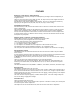
INTRODUCTION The AX4752 multi-zone audio/video amplifier combined with Axium controllers, and/or a home automation system enables you to individually control the power, volume and source selection in up to four rooms, with four Sub-zone preamplifier outputs available. Axium multi-zone amplifiers may be interconnected via the expansion bus, providing up to 32 zones of control which vastly simplifies installation cabling.
FEATURES Mulit-Zone , Multi-Source, Video Switching The AX4752 has four separate preamplifiers and amplifiers, providing 4 zones of independent yet integrated control. There are seven stereo sources (SAT, DVD, VID, AUX, CD, Tape & Tuner) and an eighth mono source (Utility) typically used for paging applications.
Presets & Paging There are six amplifier presets, and a ‘page preset’. Presets 1 - 6 are momentary and cause the amplifier to go to a predetermined setup, i.e. standby, volume & source selection. The presets may also be programmed with event scheduling, and are used by the alarm clock feature. The ‘page preset’ mode is for paging applications and is invoked by a contact closure between the ‘0V’ and the ‘PG’ terminals. When the contact closure is released the amplifier zones return to their previous states.
INSTALLATION GUIDE UNPACKING Immediately upon receiving your AX4752 inspect the carton for evidence of mishandling during shipment. Then carefully unpack the unit and inspect for damage. Please save the shipping carton and all inner packing materials in the event that the AX4752 needs to be shipped for service or moved to a new location. Should you discover that the AX4752 has been damaged during shipping please contact your dealer immediately. PRECAUTIONS 1) Never expose the unit to moisture.
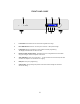
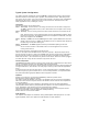
FRONT PANEL GUIDE 1 2 3 4 12:18 Master Bed On DVD 7 6 5 1 Front Panel: Solid Aluminum front Panel with Engraved Axium Logo. 2 Infra-Red Receiver: Receiver for front panel IR control – Not IR pass through! 3 LCD display: Back lit LCD display for menu guided control & programming. 7 The display is dimmed when all zones are OFF. 4 Rotary Encoder & Push Select: The display menus are navigated and selections made using left and right rotation and pushes on the knob.
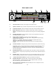
REAR PANEL GUIDE 8 9 10 230 - 240VAC 50 - 60Hz 500VA Fuse = 2.
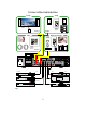
TYPICAL SYSTEM CONFIGURATION Lounge Study CD MCD TU AUX VOL DMS DVD MUTE + - Axium IRFX Receiver Controller 1 interface Zone 1 Zone 2 Gym Bedroom & Ensuite CD MCD TU AUX DMS DVD Keypad Controller 1 interface VOL MUTE 1 2 3 4 5 6 7 8 9 -/-- 0 AV CD MCD TU AUX DMS DVD VOL MUTE + + - DISC SELECT GROUP RANDOM - Axium Axium Keypad Controller 1 interface AMP Zone 3 230 - 240VAC 50 - 60Hz 500VA Fuse = 2.
Typical System Configuration: Fig 1 depicts a typical configuration, where the AX4752 is providing audio into four listening zones. Each zone consists of a room with a pair of speakers, and a suitable controller. Additionally a zone may require TV’s or screens. In Fig 1 three such screens are shown in the Lounge, Gym, and Bedroom. Each zone may be listening / watching any of the 6 connected sources: Satellite Receiver, DVD, Video, Digital Music Server, CD Changer, or Tuner.
CONTROLLER TERMINATION 0V PG 1 2 3 4 # AMP ON C D IR outputs IR1+IR2 IR2 Data 12V IR2 0V IR1+IR2 IR1 Data 12V IR1 0V Data 12V IR 0V CAT5E cable used to connect controllers to AX4752 Fig 2 The recommended wiring and colour scheme is shown in Fig 2. Use home runs of Cat5E cable. The maximum recommended cable distance from the controller to AX4752 is 200m. When +12VDC is applied to the IRFX ‘ON’ terminal the receiver module’s ‘Ampon’ indicator illuminates.
ADVANCED IR CONTROL RS232 Serial interface TA TU Expansion Bus Output 0V PG 1 UT AX4752i Multi-Room amplifier Made in New Zealand Audio Engineering Ltd +12V 2 3 4 # AMP ON C D IR outputs L IR2 Data 12V IR2 0V IR1 Data 12V IR1 0V IR1+IR2 R Expansion Bus Input CD changer SAT 2 Tuner 2 SAT 1 Tuner 1 Fig 3 IR routing - discussed in ‘Typical System Configuration’ - is used to address specific centrally located source components.
MULTIPLE AX4752 STACKS To next amplifier in the Stack 230 - 240VAC 50 - 60Hz 500VA Fuse = 2.
ZONE LINKING Fig 5 LOUNGE STUDY CD MCD TU AUX DMS DVD VOL MUTE + - Axium IRFX Receiver Controller 1 interface Zone 1 230 - 240VAC 50 - 60Hz 500VA Fuse = 2.
AUTOMATION Axium Axium 230 - 240VAC 50 - 60Hz 500VA Fuse = 2.
RS232 PROTOCOL The RS232 Asynchronous serial port provides data acquisition and control of Axium networks by a home automation system, or PC. The lead must be ‘Null modem’ : 9 pin female ‘D’ connectors at both ends (pin connections 2 and 3 swapped at one end) Only RX , TX & 0V (pin 5) are used. Baud Rate = 9600 , Characters are all ASCII. Command Structure: line feed.
Data Command Standby Mute Source Selection Volume Bass Treble Balance Amplifier features Volume Limit Preset Track Zone Content 00 – Standby A OFF 01 – Standby A ON 02 – Standby B OFF 03 – Standby B ON 04 – Toggle standby A 05 – Toggle standby B 06 – Standby A & B OFF 07 – Standby A & B ON 00 – Mute 01 – Un-mute 02 – Toggle Mute 00 – Select CD 01 – Select Tape 02 – Select Tuner 03 – Select Auxiliary 04 – Select Mono utility input 05 – Select SAT 06 – Select DVD 07 – Select Video 00 – A0 range F4 – 0C (-
Example strings: 010A01 : Standby A ON command for zone 10 amplifier 012A01 : Standby ON command for zone 10 preamplifier 060002 : +2db Treble setting on zone 0 03IF02 : Tuner source selection on zone 31 0B0311 : Volume down continuous push on zone 3 keypad Keypad key codes An Axium Keypad may be directed to emit its learnt IR commands via RS232 control. This is achieved by sending a ‘Cause key press on Keypad’ command, followed by the zone, and the Keypad key code (data).
MENU NAVIGATION Front Panel user interface: The controller has a 2 line by 16 character alphanumeric display with a Rotary Encoder and integral push button (Enter key) on the knob shaft. The AX4752 displays a hierachial menu for accessing and controlling all amplifier functions. The user navigates through the menu using left / right rotations and Encoder Knob pushes for selections or escapes.
• Primary Functions Menu 16:40 Lounge Off If the zone or room is OFF then the clock, zone or room name, power OFF and select room arrow are displayed. Selection bars are shown surrounding the lounges OFF power status. Rotating the knob left or right shifts the selection bars, so that either the power status or select room arrow may be selected.
• More Setup Function Bass: 0dB Treble : +2dB Balance: 0dB Loundness : Off Max Volume : 99 Set Zone : 4 Name : Bedroom Link Zone : none Function Bass: +4dB Treble : 0dB Balance: 0dB Loundness : Off Max Volume : 65 Set Zone : 4 Name : Ensuite Link Zone : none Preamp Volume Selecting the right arrow in the primary function menu accesses ‘More Setup’ functions. The rotary encoder steps through the list of functions. • Bass: ± 12dB of adjustment. • Treble: ± 12dB of adjustment.
PROGRAMMING USING AMC Overview; AMC is an amplifier setup utility program. Full control and tracking of any Axium amplifier zone is provided. The program runs on Win 2000, NT and XP operating systems, and communicates via either an RS232 serial or USB port. When a PC running AMC is first attached to an AX4752 the amplifier clock is automatically set to the PC’s current time and date.
Zone Select: To select the zone move the cursor over the zone tab’s down arrow and left click. A zone list window appears - make the selection with a left mouse click. Placing the cursor over the zone tab’s room description displays information about the amplifier’s device ID / serial number. Zoned Functions: • Standby: On, Off control of the amplifier or preamplifier is achieved by a left click over the standby buttons. The blue LED and the button shading indicate ‘On’ status.
• Volume Levels: The volume sliders may be changed either by left clicks above or below the displayed level, or by dragging the level down using a left click and hold. Note: If the preamplifier is in ‘Tracking’ mode then changing one volume changes the other. • Maximum Volume Limit: The maximum volume limit is set firstly by identifying the slider with a left mouse click, then on the keyboard hold down the ‘Shift’ key and adjust the level using the ‘Up’ and ‘Down’ keys.
Setup Window The window provides the means to control the occasionally used functions like bass, treble, amplifier and preamplifier balance and loudness. These are all adjusted using a left mouse click while above the button or slider. Note: The preamplifier and amplifier share the same bass & treble control. Loudness is defeated when the preamplifier is set to ‘Independent Mode’.
Preset Setup Window Preset Programming: Preset programming effects all zones on the AX4752. There are six momentary preset buttons – Preset 1 - Preset 6. These presets are stored in the AX4752, and may be setup using the AMC setup window. Left mouse click over ‘Set up preset 1’ and change any AX4752 function i.e. On status, volume level, source selection, even bass, treble etc.
Source Control Alarm Clock programming: If a KRXm Axium keypad is connected to the AX4752, then source control can also be included in an alarm preset. Open a KRXm keypad Window and select the attached Keypad’s zone. it can be made to send it’s source control commands In the preset setup window select ‘Macro’. Using the mouse with left clicks select the Keypad functions required; i.e. ‘CD select’, ‘1’, ‘2’, ‘Play’. The above sequence is entered into the macro window.
SPECIFICATIONS AUDIO • • • • • • • • • • • • Preamplifier Gain (max: Vol = 99)…………………………………………….…………………………+15dB Input Impedance ………………………………………………………………….……………………………...22KΩ Output Power…………………………………………………………………….………50 Watts RMS @ 4 – 8Ω Signal – Noise …………………………………………………………………………………...>92dB A weighted THD (1VRMS input, Gv = 0dB)……………………………………………….……………………………….0.05% Channel Separation (Gv = 0dB; f=1KHz).……………………………….……………………….…...>95dB Frequency Response …………………………………………………………….