
Instruction manual

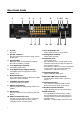
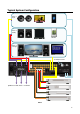

Rear Panel Guide
1 2 3 4 5 6 7 8 9 10
11 12 13 14 15 16 17 18
1 AC Inlet
IEC socket
2 Speaker Terminals
Plug in terminal clamp connectors accept 1.5mm²
speaker wires
3 Expansion Bus
RJ45 patch cable connects between expansion
bus ports of amplifiers in a stack.
4 Coax Digital Input Terminals
Coax digital (SPDIF) inputs.
5 Coax Digital Source Output Terminals
Coax digital outputs for expansion to further
amplifier zones.
6 Buffered Video Out
The composite video inputs are buffered to enable
expansion to further amplifiers.
7 CVBS Video Input Terminals
Composite (CVBS) video inputs.
8 USB for programming
USB mini B socket for programming and firmware
updates.
9 Ethernet Port
This port is used for control, monitoring and data
access.
10 RS232 Communication Port
The port is used for setup, control or monitoring.
A straight through cable must be used when
connecting to a PC or control system.
11 Zone Preamplifier Out
Analog Audio L/R Zone 7 and 8 outputs.
12 Analog Input Terminals
Analog Audio L/R inputs
13 IR Emitter Ports
3.5mm mono jacks.
IR1 and IR8 are used to control specific source
equipment, where full IR routing is assigned by
the connected controller.
IR9 & IR10 are used to control source equipment
common to all zones. These ports output the
combined IR1 – IR8 infra-red strings.
14 Optical Digital Inputs
Optical (TOSLINK) digital inputs
15 Switcher CVBS Output Terminals
Composite video matrix switcher outputs for
Zones 1 - 4
16 Controller Interface
For connection to keypads and IR receivers.
8 controller interface ports - RJ45 sockets
17 Bus Run Controller Interface
Legacy ‘BUS RUN’ port (4 way terminal block)
18 AMP ON Control
12 – 24V AC/DC powered doorbell - contact
closure between PG1 or PG2 and Common (C)
terminals Invokes a preset enabling paging or
doorbell function.
AMP-ON 1 - 8 output 12VDC when Zone is ON.
9