
User`s manual

AX2200/AX2300 Instruction Manual Chapter 4 Serial Communications
CM2-AX2000-2001 (Rev.4, 4/2014) 4-21
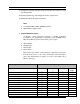
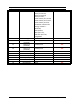
01 Device address
04 Function code 4 = read input register
00 00 Starting address
00 50 Number of registers = 80
F0 36 CRC
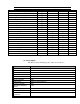
results in an error response as follows:
01 84 02 C2 C1
01 Device address
84 Function code with most significant bit set indicates
error response
02 Exception code 2 = invalid data address
C2 C1 CRC
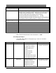
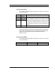
Request the state all three alarms:
01 02 00 00 00 03 38 0B
01 Device address
02 Function code 2 = read discrete inputs
00 00 Starting address
00 03 Number of inputs = 3
38 0B CRC
and the unit responds with:
01 02 01 02 20 49
01 Device address
02 Function code
01 Number of data bytes = 1
02 Alarm #2 on, alarms #1 and #3 off
20 49 CRC
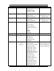
To reset the totalizer:
01 05 00 00 FF 00 8C 3A
01 Device address
05 Function code 5 = write single coil
00 09 Coil address = 9
FF 00 Data to reset totalizer
5C 38 CRC